Synth Cafè intervista: Garretlabs (Marco Lastri)

A great interview (in Italian) on Synth Cafe’ blog, by the friend Luca Minelli.
I am very excited for this…. and I am very happy for this beautiful opportunity to talk about me, my project, my music, my life.
Because during these years (during this “silenc” on my tech blog… 😦 ) , my activities and my life slightly change. And now you can see what happened…. 😉

Il blog di Synth Cafè

Chi è Marco Lastri?

All’inizio volevo fare la classica domanda a Marco, ma devo dirvi la verità: Marco è come lo leggete: una persona ricca, ricchissima di entusiasmo e voglia di fare. Probabilmente la persona con più entusiasmo creativo che io conosca. Ci siamo incontrati dal vivo al MEFF di Firenze e abbiamo chiacchierato un pò, con la promessa che ci saremmo risentiti.

Ed eccoci qua. Non ci sono praticamente domande: è Marco a raccontarsi.

Leggete e prendete spunto. Dico davvero.

Luca

primopiano Marco Lastri (Garret Labs)

M.L.: Ciao a tutti! Prima di iniziare vorrei innanzitutto ringraziare Luca Minelli, per il suo straordinario in Synth Cafè e per avermi dato la possibilità di poter presentare il mio lavoro come Garretlabs, questo piccolo marchio artigianale che mi sono inventato qualche anno fa (grazie a Monica per il suggerimento e per il design del logo stesso!) e che adesso sto cercando di far…

View original post 3,025 more words

MeeBlip Anode “Italian Way”: monophonic synthesizer with OLED display (and an overclocking option)

Goooooood evening dear makers! (and, in this case, I hope also musicians! 😉 )

It’s toooooo much time that I work on my projects without new posts, and I apologize for this.

The fact is that I have -as you know- many activities in parallel to making open source *ware projects: my work (I work in the frame of space projects for artificial satellites, for example I uploaded a little part of me on JUNO, and especially on the Italian part of Juno: the JIRAM instrument), my music (I play in some bands, and I also produce a lot of solo music: check it out  and download all at www.marcolastri.net ) … and obviously my family!!! 🙂

So, since time is short… and life is too short, let’s start.

We can start from this beautiful project: Meeblip Anode.

It is a great monophonic synthesizer based on ATMEGA32P, with a really great sound, very deep and powerful.

…Have a look to demos on Youtube for the proof of what I’m writing.

I loved the MeeBlip Anode sound from the first time I heard it. In Italy we call this feeling “Amore al primo ascolto”…. 😀

And to me, the greatest thing of MeeBlip Anode is that this incredible project is completely (hardware and software) open source!!! You can buy a pre-built one, but you can also self-produce it in order to play it with your band or to modify/hack it (or both the things, like me ! 😉 )

Well.  I obviously self-produced one prototype of Anode and I started to play it in my music projects, but I wanted to add some (in my opinion) important functionality to this great project.

The idea has been of my father Gualtiero which, looking me playing with Anode and modifying the position of potentiometers, said to me: “It sounds very good… but… in which way you know the values for potentiometers?”

Woooow, thanks dad! It was the idea: add a numerical/visual indication of pots values using a display. An OLED display (because the OLEDs don’t have the backlight regulation…so less electronics to add! 😉 ).

And I decided to call this mod “Italian Way” because in Italy we always need visual information. For example think to our famous gestures when we (try to) talk in English to tourists to give them indication on the streets of our cities. 😀

So, I decided to proceed in the following way:

  1. Look in the electronic schematic if ATMEGA32P has some free GPIO to be used in order to command the display (at minimum 6  pins, which is the minimum for commanding the great part of displays)
  2. Since the Meeblip code is written in AVR assembler, download and study the datasheet (and instruction set) of the ATMEGA32P. I was a good assembler programmer once upon a time…but now I am a little older, so… 😉
  3. Find a good AVR driver or set of subroutines for commanding display, written in assembler
  4. Decide which synth values to display on the OLED!
  5. Modify these subroutines in order to display in quasi-realtime, and integrate them in the original code
  6. Modify the original Meeblip code in order to use the display subroutines.

Well…the work has been long (long, long, very long and again looooooooong) and hard (hard, very hard… etc.).

But I think it has been a great work! 🙂

I uploaded all the code on GitHub. I dont know if I well done all the process, but this is the first time with GitHub for me…. 😉

For the project I realized a new branch from the official one. So you can download all my code from: https://github.com/garretlabs/meeblip-anode/tree/meeblip_anode_italian_way

The GPIO pins to be used

I had been lucky: the MeeBlip Anode has some free (and not connected) GPIO on the microcontroller, so they can be freely used to command a display.

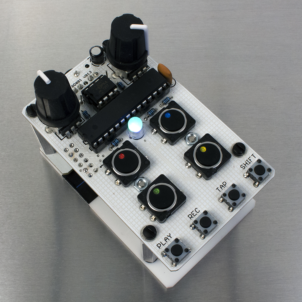
They are reported in the following photo:

20160415_182624

I decided to use an OLED display by Newhaven ( Mouser code 763-NHD-0420DZW-AG5), which will use 4 pins for data (+ 2 pins for Enable and RS) chosen from PB0, PB1, PB2, PB3, PD2, PD5 and PD6 (plus 5V and GND).

The mapping used for the connection between  the display and the ATMEGA32P has been the following:

  • Display pin 1 (Vdd): VCC
  • Display pin 2 (Gnd): GND
  • Display pin 6 (data 0): PB0
  • Display pin 7 (data 1): PB1
  • Display pin 8 (data 2): PB2
  • Display pin 9 (data 3): PB3
  • Display pin 4 (RS): PD5
  • Display pin 5 (E): PD6

So… I solded the pins of ATMEGA32P to display pins using a 9 pins male/female connection (such as a simple serial connection). The result has been the following:

20160415_133043-1

The datasheet and code study

Simple step…but very tricky! 🙂

Well, during this step I downloaded the Atmel Studio 6 (freely available) and I wrote some example code, I used the debug function on the simulator and then I created a project based on the Meeblip Anode original code downloaded from Github (and obvioulsy I succesfully recompiled it).

The display driver written in AVR assembler and his

I found a really good set of subroutines written in AVR assembler for ATMEGA328 (but it is working also on ATMEGA32P) to command displays using 4 wires. This is the complete code from which I started.

I created the file LCD.inc, and I added it to the Atmel Studio project. Obviously I changed the GPIO assignments in order to match to GPIOs used in my situation. I also added some modification regarding the fact that I would like to display values taken from the RAM of the microcontroller and not from the program memory (as is in the driver). This is the fundamental modification, at line 786 of file LCD.inc:

;lpm     temp_lcd, Z+   ; ///ML: removed since this instruction read from Program Memory
ld    temp_lcd, Z+      ; ////ML: get a character from RAM

And I also added some ad-hoc subroutine to be used in the frame of the modified MeeBlip code. They are the main ones:

  • MYLCD_PREPARE_GUI is the subroutine which prepare the display inserting the fixed labels (they wont change during normal operation of synth).
  • MYLCD_UPDATE is the main subroutine used to refresh the display (pots values and switches status). It refreshes tha display on every 100 milliseconds.
  • MYLCD_CLEAR is used to clear all the display

Note also that in order to display numeric values in the display, a conversion between the values and his correspondent string should be done. For this I found online a very simple subroutine which is called in order to have the values to display in ascii format. This is the subroutine contained in the file SimpleASCIIConversion.inc:

HEX_2_ASCII:
bcd: 
   ldi r18, -1 + '0' 
_bcd1: 
    inc r18 
    subi r16, 100 
    brcc _bcd1 
    ldi r17, 10 + '0' 
_bcd2: 
    dec r17 
    subi r16, -10 
    brcs _bcd2 
    sbci r16, -'0' 
ret 

Well…  now we can include and use the file LCD.inc inside the original MeeBlip code.

Synth values to display on the OLED

I chose to display the values directly tied to the potentiomenters position and to switches positions. But it is only an idea: you can decide to display also other parameters. 😉

In this hand-made drawing you can see the Anode panel with the names of global variables tied to pots and to switches.

20160725_073555-1

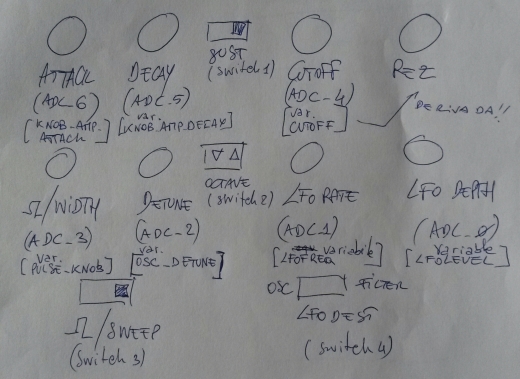
Under each switch you can see the switch number to refer in the code. Under each potentiomenter (in the [] parentheses) you can see the name of the variables used to memorize the pot values.

Note that the pot on the bottom-left is used for two purposes (waveform and width), depending on the position of switch 3. The real variable names for this pot are the following (I know, the drawing is not updated to the last revision of my code…. but I loved to report it in my post 😉  ): WAVETABLE and PULSE_KNOB_LIMITED.

So in the code I managed this in order to display the right values depending on the siwtch position. You can see in file LCD.inc at the labels DISPLAY_WAVETABLE_VAL and DISPLAY_SWEEP_VAL. The choice of the path is done at lines 301 to 303, analyzing the current (and saved in a temporary variable) position of the switch 3.

The other variables names to display reported in the drawing should be OK…. I hope! In any case you can refer to the code, which ever says the truth! 🙂

Integration with Meeblip original code

I included the file LCD.inc after the inclusion of file “subroutines.inc”.

I defined some variable in variable_definition.inc:

///ML 20x4 lcd strings (4 rows of 20 chars+'\0')
my_LCDstring4: .byte 21
my_LCDstring3: .byte 21
my_LCDstring2: .byte 21
my_LCDstring1: .byte 21

//ML temporary variable in RAM
temp_in_RAM: .byte 1

After this, in the main program, the LCD is initialized using:

rcall LCD_START
//---start delay routine
push r18
push r19
push r20
; Generated by delay loop calculator
; at http://www.bretmulvey.com/avrdelay.html
;
; Delay 8 000 000 cycles
; 500ms at 16.0 MHz

    ldi  r18, 41
    ldi  r19, 150
    ldi  r20, 128
L1: dec  r20
    brne L1
    dec  r19
    brne L1
    dec  r18
    brne L1

pop r20
pop r19
pop r18
//----end wait routine---
rcall MYLCD_CLEAR
//prepare LCD gui (not to be refreshed at each basic cycle!)
rcall MYLCD_PREPARE_GUI

Then, the display refresh routine is called at each cpu cycle using:

rcall MYLCD_UPDATE

Note that, since the memory occupation has been increased, I had modified  some “rcall” instruction in “call”. You will find these changes searching for this comment:

//ML--->>changed rcall in call to avoid error " relative branch out of reach"

Well, that’s (mainly all)!

Recompiling the code and burning the binary on the ATMEGA32P you should obtain (after a screen reporting the name and the version of the synth) something like this:

20160719_191421

I’m sorry for the bad picture…but I was so excited! 🙂

The tests using the synth have been all successful, that is:

  • MIDI IN is OK (no MIDI note is lost during play)
  • Audio is OK (the notes produced with the working display have the same waveforms of them produced by the original Meeblip Anode firmware, I tested it with oscilloscope)
  • The interaction with the pots and switches are OK (the refresh of values on the display is very fast respect to the actions on the pots and switches).

So…it seems that a refresh rate of 100 milliseconds should be a good choice for ATMEGA32P computational load!

This is my MeeBlip Anode “Italian Way”, and now, after this great ordeal, I am ready for a (big) glass of Italian grappa. 🙂

I recall here the link to the code in GitHub: https://github.com/garretlabs/meeblip-anode/tree/meeblip_anode_italian_way

…Bonus Easter Egg (for die-hard geeks only): overclock it!

I am an old style geek… some years ago one of my hobbies was to overclock the CPUs of my computers.

I know that ATMEGA32P can be connected to a crystal with maximum frequency of 16Mhz (following the datasheet). But…I love the risk (hmmmm…. only on electronics things! 😉 ) so I wanted to connect him to a 20Mhz crystal.

With some basic code modification, you can have your overclocked Meeblip Anode “Italian Way”.

These are the modifications.

Firstly in the anode.asm file we change the cpu frequency:

.SET cpu_frequency = 20000000 //ML changed the CPU frequncy to 20Mhz

The other basic modification is the Timer 0  initilization (which is the hearth of the MeeBlip sound generation):

;initialize Timer0:

      //ldi     r16, 49             ;\  ; Set sample rate to 40.00 kHz //ML---> commented, since we need a new prescaler value
      ldi     r16, 62                ;\  ; Set sample rate to 40.00 kHz: ML---> we use 62 if the clock is 20Mhz since 16Mhz:49=20Mhz:x... in this case we have always the note in tune!
      out     OCr0, r16           ;/ OCr0 = 49 (///ML---> 62 on overclocked version) gives 40000.00 Hz sample rate at 400 cycles per sample loop.
      ldi     r16, 0x0A           ;\ clear timer on compare,
      out     TCCr0, r16          ;/ set prescaler = CK/8

Note that I used the value 62 for r16, instead of theoretically correct value 61, since I used a software tuner to have the best sound (Tunafish for MacOSX) and trying the values around 61.
Then I add a warning also in the initialization of Timer 2 PWM controlling cutoff…

ldi      r16, 0b01100001     ; Phase correct PWM, no prescaler ///ML WARNING: verify if the soud is nice with 20Mhz clock, else adjust!!!

For me the sound is nice…. 😉

In the LCD.inc file you should finally set the new frequency:

.equ    fclk      = 20000000      ;///ML---->new  system clock frequency (for delays)

This should be all for this easter egg… but I think you should do many other improvements of the code!

I had no problem and I played (and I’m playing) with great satisfaction the overclocked synth in my home studio for several projects…. but note that nothing is guaranteed with this mod. So handle with care! 😀


Phhhhhheeeeewww (I can rebreath now :-D)….Well geek boys & girls, that’s really all for this time.

It was a long time without a post on Garretlabs, but with this one I think I paid my debt with DIY community and to Garretlabs readers!

Bye bye folks… and keep always in touch with Garretlabs!

My experience with PCBWay.com!

Goooood morning Internet (of things sure, but overall of human beings and nerd people)!

This time I would like to talk briefly about the very good experience that I had using the PCBWay (http://www.pcbway.com) online service for my PCB production.

All started when I decided, some years ago, to start producing on myself the PCBs for some of my projects . But I don’t like home-made results, so I looked for a great time for a very professional online service, with low prices and great quality. Mhhhh….difficult task! 😉

After a long discussion, a work colleague (the Brain of the well known italian site http://www.oscilloscopio.it) recommended to try the service PCBWay.com, because, he said, “the price of PCBWay is the best on the Internet”.

So…I tried it with a free online quotation…and I saw he was right (and I was sure of this). 🙂

No problem, I had at that time a project waiting to be produced so, I tried PCBWay. And I was super-satisfied. No joke boys (and girls).

This company works very well, with very small prices and great quality of produced PCBs.

The site has a very simple interface and the files used by PCBWay for production are the standard Gerber and Excellon files produced by Eagle, Kicad etc.

Well, the production time is very (very) short, 3-4 days …and the delivery time from PCB Way to my house (as you know I’m from Italy) is shorter than a standard packet from my city to another italian city using (express) Italian Postal Service (Paccocelere Poste Italiane). 🙂

….Obviously, since they use DHL as express courier… all it’s guaranteed. 😉

You can see here some of PCBs produced for me by PCBWay (sorry for the not so good quality of photos). All boards that I produced are on 2 layers, and I used  various colors. All produced boards have been excellent!


20150917_065406.jpg

20160203_170928.jpg

I’m very satisfied with this company, so I recommend it to all you my dear geeks!

Bye bye…. and…in the next days I will publish a surprise, so keep in touch! 😉

I’m not dead. I’m only (terribly) busy! :-(

Hi techo girls and boys!
I know…I know.
It’s more than one year that I don’t publish new posts on Garretlabs.
The fact is tied to new engagements: on the work (yes, I have a work which is very important to me and I want do the best on it…), in the frame of my family.
And I have also (of course) new musical projects,as composer and musician (please,check out my italian music site, and dowload for free all my compositions: http://www.marcolastri.net) but also as project engineer  and producer of noise machines and analog and digital synthesizers.
For example, for the friend Stefano Muscas of great band “Correlazione quantistica” (please, visit the facebook page: https://www.facebook.com/correlazionequantistica) I designed an produced a very interesting noise machine based on Arduino, called ALGOnoise.

image

I took the idea from here: http://little-scale.blogspot.it/2008/01/arduino-noise-maker-info.html but I added some modification (a repetition function, an output amplifier and some funny values changes on the resistors). I will publish very soon the result on Garretlabs (I hope)!
Here you can see a live concert of Correlazione Quantistica with Stefano playing ALGOnoise (yes, it’s the yellow box 🙂 ):

image

image

image

I’m very honoured of this collaboration!
After this I produced a modified version (the modification are: all controllers are panel mounted, the on-off button can be bypassed by a switch pedal, double resonance potentiometer and an adapter for the use with a power supplier) of the well known SparkPunk by Sparkfun. I did it for my friend Alessandro “Mazza”, the singer of the historical italian demential-metal band Tossic (http://www.tossic.it/home.html).
Here you can see the naked machine called “Mazzulator”:

image

I’m very excited to work with Alessandro, since I love his band from ever. I was 14 when I encountered for the first time the politically uncorrect world of heavy metal, and the first disc I listened was “Il Regno del Cingliale” of a strange and demential band called Tossic: one of the first italian heavy metal bands. Now I am 40, an d I love Tossic as the first day. 😉

Well… after this I produced some other music/noise machines, especially guitar effects pedals For example, I built an echo/delay and a chorus pedals for my friend and guitar player Fabiano Vezzosi, and I modified a model of the well known pedal “Metal Zone” (by Boss) in order to transform this pedal in a great fuzz effect. It kicks asses now! 😉

I also modified a great number of other guitar pedals of many friends…But in the meantime I produced also some other interesting things: for example new versions of old (diy) synthesizers. :-O

…But it is another story: keep in touch to discover this “dark side of Garretlabs”. 🙂

RasPI-Surv: a Raspberry-based scalable SMS remote controlled video surveillance system

Good morning dear security systems fanatics Garretlabs fans!

Today you will be very interested in my new post, I’m sure.

Because today we talk about a high-scalable videosurveillance system called RasPI-Surv, based on:

  • A system controller based on Raspberry PI
  • A practical (and modifications-friendly) command/telemetry interface via SMS messages, using the very well known SIM-900 module from ITEAD.
  • A set of wireless video cameras with good motion detection feature
  • A internet router/modem with wireless access point
  • A Google Mail account (it will be your “house account”), to be accessed via IMAP.

I engineered this system after a very strange request from one of my strangest friends. 🙂

He was looking for a “internal” videosurveillance system with motion detection to be used only during his vacation periods…and after the vacation periods he wanted to disable the system and put all cameras and controller inside a box! 😉

In other words he wanted a “portable” internal video surveillance system, without in-the-wall connections, without fixed positions for the cameras, so a very dynamic system with the opportunity to move the cameras and the controller inside his house. Plus, he wanted a powerful and portable alarm siren to be placed in his house, without external components (please note that this DIY solution is not accepted by italian laws, so in our country the alarm device must be always placed by a devoted an credited technician).

A practical example of the siren 12V powered could be THIS  …but you can buy another model following your needs.

Thinking for a smart solution, I studied a system with two day-night wireless IP Cameras from HooToo with pan and tilt features (http://www.hootoo.com/hootoo-ht-ip211hdp-indoor-wireless-network-camera-with-ir-cut-black.html) and two day-night D-Link fixed cameras (http://www.dlink.com/it/it/home-solutions/view/network-cameras/dcs-932l-day-night-cloud-camera). But you could add/remove wireless IP cameras with motion detection featire (also of different brands), in order to add/remove “eyes” to your system.

So, this is a very scalable solution. 😉

Firstly I placed the cameras near a wall power socket (ok, they are wireless..but unfortunately they need power… 😦 ), then I connected all cameras to the internet modem/router following their own user guides.

Finally I enabled their motion detection feature with the email sending (using the “house Google Mail account”) of the captured frame when a motion is detected.

Note that for some camera, a fast tramsition from day to night vision and viceversa (i.e. a sun ray refled by a passing car in the street) could be recognized as motion (so as a false alarm by the system 😦 )…so the best way to place the camera is in front of closed external doors without glasses and of closed windows with the rolling shutter completely closed.

Well… do you placed the alarm siren and cameras? Have you configured your cameras in order to connect to your modem/router and to send an email using your Google mail account when a motion is detected? Very well… we can go ahead with the system idea.

This is the overview schema of the system (as always drawn by hand by me, sorry for the bad photo! 😉 ):

wpid-2014-11-10-08.37.09.jpg.jpeg

…In practice at this moment we have all cameras connected to our modem/router and a alarm siren connected to the power thru a relay commanded by the Raspberry PI. So, we must to setup the Raspberry PI in order to execute the following operations/requirements:

  • Periodically it should check the SENT folder of your Google Mail account, in order to verify if one of your IP cameras detected one motion (and so they sent an email using your “home account”). The cycle should be fast because one burglar can be very fast to open a window and to move in your house… 😦
  • If one or more email arrived from your cameras, it should activate the relay in order to power ON the alarm siren
  • In this case it shoud send an SMS to your mobile phone in order to advise you that the siren has been powered ON
  • It should manage a set of SMS commands in order to: force the power OFF of the alarm siren, enable and disable the check of the sent emails, cancel the SMS memory of the SIM900 module, reset or reboot the system etc.
  • It should send a set of SMS in order to advise you that there is some problem (i.e. the internet connection is down, so the Google Mail mailbox can’t be accessed).

Well. It is’nt so difficult to implement it all. If you you read first these previous posts from Garretlabs: THIS ONE (it uses a GSM dongle and the software gammu in order to receive/send the SMS messages, plus to command the GPIO pins of Raspberry using Python) and also THIS ONE (it uses the SIM900 module and the AT commands in order to receive/send the SMS messages).

This is the Fritzing schema of the controller Raspberry PI+SIM900 module used to command the relay for the alarm siren:

Video surveillance controller (finale per uso con SIM900) v2_bb

I propose you the complete code of my project…. so you can now start playing with the RasPI-Surv system


#! /usr/bin/env python

import RPi.GPIO as GPIO
import imaplib, re, time, serial, subprocess

#class from http://segfault.in/2010/07/playing-with-python-and-gmail-part-1/ and http://segfault.in/2010/08/playing-with-python-and-gmail-part-2/
class pygmail(object):
    def __init__(self):
        self.IMAP_SERVER='imap.gmail.com'
        self.IMAP_PORT=993
        self.M = None
        self.response = None
        self.mailboxes = []

    def login(self, username, password):
        self.M = imaplib.IMAP4_SSL(self.IMAP_SERVER, self.IMAP_PORT)
        rc, self.response = self.M.login(username, password)
        return rc

    def get_mailboxes(self):
        rc, self.response = self.M.list()
        for item in self.response:
            self.mailboxes.append(item.split()[-1])
        return rc

    def get_mail_count(self, folder='Inbox'):
        rc, self.response = self.M.select(folder)
        return self.response[0]

    def get_unread_count(self, folder='Inbox'):
        rc, self.response = self.M.status(folder, "(UNSEEN)")
        unreadCount = re.search("UNSEEN (\d+)", self.response[0]).group(1)
        return unreadCount

    def get_imap_quota(self):
        quotaStr = self.M.getquotaroot("Inbox")[1][1][0]
        r = re.compile('\d+').findall(quotaStr)
        if r == []:
            r.append(0)
            r.append(0)
        return float(r[1])/1024, float(r[0])/1024

    def get_mails_from(self, uid, folder='Inbox'):
        status, count = self.M.select(folder, readonly=1)
        status, response = self.M.search(None, 'FROM', uid)
        email_ids = [e_id for e_id in response[0].split()]
        return email_ids

    def get_mail_from_id(self, id):
        status, response = self.M.fetch(id, '(body[header.fields (subject)])')
        return response

    def rename_mailbox(self, oldmailbox, newmailbox):
        rc, self.response = self.M.rename(oldmailbox, newmailbox)
        return rc

    def create_mailbox(self, mailbox):
        rc, self.response = self.M.create(mailbox)
        return rc

    def delete_mailbox(self, mailbox):
        rc, self.response = self.M.delete(mailbox)
        return rc

    def logout(self):
        self.M.logout()

#end library/class

##############################################################################
#Functions to PowerON OFF the relay
##############################################################################
#poweron the relay
def PowerONRelay():
    GPIO.setup(22,GPIO.OUT);
    GPIO.output(22,GPIO.HIGH);
    return;

#poweroff the relay
def PowerOFFRelay():
    GPIO.setup(22,GPIO.OUT);
    GPIO.output(22,GPIO.LOW);
    return;

##############################################################################
#Functions to manage SMS
##############################################################################
#check unread arrived messages
def CheckNewUnreadMessage(ser):
    print "Check for new messages..\n";
    ser.write("at\r");
    time.sleep(3);
    line=ser.read(size=64);
    #print line;
    ser.write('AT+CMGL="REC UNREAD"\r')
    time.sleep(3);
    response=ser.read(size=200);
    print response;
    return response;

#function to send confirmation SMS
def SendSMS(ser,value):
    #send SMS about the action
    ser.write("at\r");
    time.sleep(3);
    line=ser.read(size=64);
    print line;
    ser.write('AT+CMGS="+391234567890"\r'); #here put your phone number :-)
    time.sleep(3);
    if (value==1):
        ser.write('ALARM ON!\r');
    elif (value==0):
        ser.write('ALARM OFF!\r');
    elif (value==3):
        ser.write('ALARM enabled!\r');
    elif (value==4):
        ser.write('ALARM disabled!\r');
    elif (value==11):
        ser.write('ALARM commanded OFF (was ON)!\r');
    elif (value==20):
      ser.write('Deleted SIM memory!\r');
        elif (value==50):
      ser.write('INTERNET DOWN!\r');
    elif (value==51):
      ser.write('INTERNET UP!\r');
    elif (value==60):
      ser.write('Warning: GMAIL temporary DOWN!\r');
    time.sleep(3);
    ser.write(chr(26));
    return;

#function to delete messages...(GSM900 stores only 30 messages..)
def DeleteAllMsg(ser):
    ser.write("at\r");
    time.sleep(3);
    line=ser.read(size=64);
    print line;
    print "Deleting memory....";
    ser.write('AT+CMGD=1,4\r');
    time.sleep(3);
    return;    

###############################################################################
#main program for alarm check
###############################################################################
#global variables
initials_sent_emails=0
ALARM_enabled=True
ALARM_ON=False
actual_sent_emails=0;
ALARM_ON_cycles=0;
INTERNET_UP=True;
GMAIL_UP=True;
################################################################################
#functions to enable/disable/stop alarm (sent VIA SMS)
################################################################################
def enable_ALARM():
         global ALARM_enabled
         ALARM_enabled=True
         

def disable_ALARM():
         global ALARM_enabled
         ALARM_enabled=False
         

def stop_ALARM():
        global initials_sent_emails
        global actual_sent_emails
        #ALARM_ON=False
        initials_sent_emails=actual_sent_emails
        #ALARM_ON_cycles=0
        #TODO here send SMS telemetry

################################################################################
#MAIN program
################################################################################

#0: power ON the SIM900 module and waits for SIM registration
GPIO.setmode(GPIO.BCM)
GPIO.setup(17,GPIO.OUT)
GPIO.output(17,GPIO.HIGH)
print "Registering the sim...\n";
time.sleep(15); #wait for sim to register to the net
#0a: open serial link on /dev/ttyAMA0. It is open only one time:it remains open for all operation time.
#No more open+close action is now requested.
print "Opening communications serial...\n";
ser=serial.Serial('/dev/ttyAMA0',9600,timeout=1);
ser.open();


#1: first login to Gmail
g = pygmail()
g.login('your.home.mailbox@gmail.com', 'yourpassword')
print g.response

#2: list mailboxes
g.get_mailboxes()
for item in g.mailboxes:
  print item

#3: get number of sent emails at power ON of alarm controller...
g.get_mail_count('[Gmail]/Posta inviata')
print g.response
sent_number=g.response[0]
initials_sent_emails=int(sent_number) #actual number of sent messages
print initials_sent_emails

#4:logout from gmail
g.logout();


#Here we add the infinite loop (once per 10 seconds?) which:
#a. checks the number of sent emails (login+get_mails_count+logout)
#b. if the number is > initials_sent_emails sets (&& the alarm is ARMED) the alarm relay ON, else sets the alarm relay OFF
#b2. if this is the first time the alarm is ON, send SMS to communicate the ALARM is correctly ON!
#c. checks if a NEW SMS is arrived in order to enable/disable ALARM relay, and update the global variable
#d: waits for 10 seconds (TBC)
while (True):

       #a0: check for internet status
    ip="www.google.it";
        ret=subprocess.call("ping -c 1 %s" %ip,
        shell=True,
        stdout=open('/dev/null','w'),
        stderr=subprocess.STDOUT)
    if (ret==0):
         print "INTERNET UP!"
        if(INTERNET_UP==False):
            INTERNET_UP=True;
            SendSMS(ser, 51);
    else:
        print "INTERNET DOWN!"
        if (INTERNET_UP==True):
            INTERNET_UP=False;
            SendSMS(ser, 50);

    
       #a: check new sent messages
    if (INTERNET_UP==True):
            print 'Check new sent messages...'
        try:
                g.login('your.home.mailbox@gmail.com', 'yourpassword')
                g.get_mail_count('[Gmail]/Posta inviata')
                actual_sent_emails=int(g.response[0])
                g.logout();
            GMAIL_UP=True
        except imaplib.IMAP4.error, err:
            print 'GMAIL IMAP temporary unavailable!!!'
            if (GMAIL_UP==True):#the first time it sends an sms...
                SendSMS(ser,60)
                GMAIL_UP=False        

        #b/b2: alarm management
        print 'Alarm management...'
        if(ALARM_enabled==1 and actual_sent_emails>initials_sent_emails):
                print 'ALARM ON!!!'
                ALARM_ON=True
                ALARM_ON_cycles=ALARM_ON_cycles+1;
                #here we command the relay ON
                PowerONRelay();
                if (ALARM_ON_cycles==1):
                        SendSMS(ser,1);
                
        else:
                if(ALARM_ON==True):
                        SendSMS(ser,0); #if the alarm is already OFF, dont send messages...
                ALARM_ON=False
                ALARM_ON_cycles=0;
                #here we command the relay OFF
                PowerOFFRelay();
                print 'ALARM OFF!'

        #c: new SMS arrived management
        print 'SMS management'
    message=CheckNewUnreadMessage(ser);
    if(message.find("enablealarm")<>-1):
        enable_ALARM();
        #send message to my phone that Relay is ON
            SendSMS(ser, 3);
        print "Alarm enabled commanded\n";    
    elif (message.find("disablealarm")<>-1):
        disable_ALARM();
        SendSMS(ser, 4);
        print "Alarm disabled commanded\n";
    elif (message.find("alarmoff")<>-1):
        stop_ALARM();
        #send message to my phone that telemetries are OFF
          SendSMS(ser, 11);
        print "Deactivated alarm\n";
        elif (message.find("delsms")<>-1):
        DeleteAllMsg(ser);
        SendSMS(ser,20);

       
        #d: basic cycle time
        print 'Wait for new cycle...'
        time.sleep(2);


Weeeeeeell….I Hope the code is well commented,so it is not so unreadable! 😉

As you see, I used a very nice Python library in order to connect to Google Mail using IMAP. You can download it from Segfault.in, and you can find good examples in the following pages: http://segfault.in/2010/07/playing-with-python-and-gmail-part-1/  and http://segfault.in/2010/08/playing-with-python-and-gmail-part-2/.

…Anyway, if you want to request some detail…I am here for you! 🙂

And as usual, if you want to comment/modify/correct/redistribute/relink my code and my idea, you ‘re free to do it (…and thanks for the your pingbacks and for credits in your blogs etc. 😉 )!

Bye bye geek guys and girls… it’s time for me to go to install and test the system in my friend’s house (also if it’s too late for his vacation time..ah ah!!!)! 🙂


…and now ANOTHER music post: SparkPunk Sequencer MIDI synchronisation with Arduino (work in progress)

“Tunz-tunz-tunz” 😀 my dear geek-musician friends (female and male of course)!

Today I used for you my “house-disco-techno”-style “hello”, because today I wan t to talk you about msuica (again).

Some day ago I bought from my preferred store (RobotItaly, as you know), and I assembled two new exciting toys from Sparkfun: Sparkpunk Sound Generator and SparkPunk Sequencer.

The Sparkpunk Sound generator is a very interesting sound generator similar to the famous ATARI Punk Console,  The Sparkpunk Sequencer is a control voltage step sequencer used to control the the Sound Generator.

After the assembly of the two devices, I played some hour with these objects… but, as you know, I am a (pro-am) musician, and I would like to have a MIDI IN  port in all my instruments. Because I attach my devices to my DAW (digital audio workstation, examples are: Steinberg Cubase, Ableton Live, Cakewalk Sonar, Apple Logic Pro etc.) resident on my computers (Mac or PCs), and my DAW  is ALWAYS the MIDI master for my set of instruments. I should command the tempo, the start and stop of my devices.

Before to do my modifications, I printed (and read) the following IMPORTANT page: https://learn.sparkfun.com/tutorials/sparkpunk-sequencer-theory-and-applications-guide . So, firstly I followed the steps for modifications in the section “Synchronizing Multiple Sequencers” and I opened the connections between IN and OUT for the pins CLK, BTN, RUN, STOP (and I used jumpers in order to re-close them again, in case the sequencer isn’t controlled from another device and it used stand alone).

After this, I thinked to use an Arduino UNO as interface between my MIDI master (the DAW) and the Sparkpunk Sequencer in order to force the Sparkpunk Sequencer to follow the MIDI clock of the DAW. This is the actual setup of my experiment:

wpid-20141021_071110.jpg

Well, the PC (Midi OUT port) to Arduino (MIDI IN port) is not difficult: it’s a very simple circuit described in one of my old posts. Using this setup the MIDI in signal pin will be connected to the Arduino D10 pin via SoftSerial.

In order to build logicaly and electrically the interface between Arduino and the SparkPunk Sequencer I studied the signals on the CLK IN, BTN IN, RUN IN, STOP IN pins in the Sequencer stand-alone configuration (so the CLK IN is connected to CLK OUT, BTN IN is connected to BTN OUT, RUN IN is connected to RUN OUT and STOP IN is connected to STOP OUT… using my preferred tools: the jumpers!).

I studied them connectinfg the oscilloscope on the pins and pressing the Run button on the Sequencer in order to start and stop the sequence. These are the results (drawn by hand… it’s so stylish and vintage! 🙂 ):

wpid-storageemulated0DCIMCamera2014-10-21-07.58.15.png.pngWell… as you see the behavior is very simple. And we can simply replicate it using Arduino with the following logic:

  • When Arduino receives from DAW the MIDI START message it commands the RUN IN pin high, the STOP IN pin  low and BTN IN pin firstly high and after a short delay (I used 5ms and it works…but you can measure the real value with the oscilloscope if you want) it commands it again low.
  • When Arduino receives from DAW the MIDI STOP message it commands the RUN IN pin low, the STOP IN pin high and BTN IN pin firstly high and after a short delay (I used 5ms and it works…but you can measure the real value with the oscilloscope if you want) it commands it again low.
  • The CLK IN value is commanded by Arduino following the reception of the MIDI CLK message, in order to synchronize the tempo of Sparkpunk Sequencer with the DAW tempo.

IMPORTANT Note: a standard MIDI CLK message is sent by a DAW 24 times per quarter note. A time of 120 BPM (beats per minute) is equivalent to 120 quarter notes per minute, so in this case the DAW sends from the MIDI out (120*24)/60 messages per second. It’s too much for our Sparkpunk sequencer (if you sends all these messages to ther sequencer, it doesn’t work…and you can’t see the ON/OFF of the Rate led).

So I decided to send to the SparkPunk sequencer only one MIDI CLK message per 24 received by the MIDI IN port on Arduino. In other words Arduino decreases the rate of MIDI CLK message in order to correctly command the sequencer.

Regarding the hardware connections, the are very simple:

  • Connect the Arduino GND to a GND point of the Sparkpunk system (i.e. the ground of the Speaker port on the Sound Generator)
  • Connect the Arduino pin D2 to the RUN IN of Sparkpunk sequencer
  • Connect the Arduino pin D3 to the STOP IN of Sparkpunk sequencer
  • Connect the Arduino pin D4 to the CLK IN of Sparkpunk sequencer
  • Connect the Arduino pin D5 to the BTN IN of Sparkpunk sequencer

This is the simple Arduino code:

#include <SoftwareSerial.h>
SoftwareSerial MidiSerial(10, 11); // RX, TX

byte midi_start = 0xfa; 
byte midi_stop = 0xfc; 
byte midi_clock = 0xf8; 
byte midi_continue = 0xfb; 
int play_flag = 0;
byte data;

//synchro values
int number_of_received_clocks=0;

#define MAX_BPM 160
#define MIN_BPM 20

void setup() 
{ 
  MidiSerial.begin(31250); 
  Serial.begin(115200);
  //led 13 used for debug
  pinMode(13, OUTPUT);
  digitalWrite(13, LOW);
 
  //interface --->Sparkpunk sequencer
  pinMode(2,OUTPUT);
  digitalWrite(2,LOW); //midi start sequencer
  
  //interface --->Sparkpunk sequencer
  pinMode(4,OUTPUT);
  digitalWrite(4,LOW); //midi synch sequencer
  
  //interface --->Sparkpunk sequencer
  pinMode(3,OUTPUT);
  digitalWrite(3,HIGH); //midi stop sequencer
  
  //interface --->Sparkpunk sequencer
  pinMode(5,OUTPUT);
  digitalWrite(5,LOW); //button sequencer 
}

void loop() 
{
  if(MidiSerial.available() > 0) 
  {
    data = MidiSerial.read();
     if(data == midi_start) {
       Serial.println("Start Midi");
       
       //sparkpunk interface commands
       digitalWrite(2,HIGH);//start/run sequencer
       digitalWrite(3,LOW);//stop sequencer
       digitalWrite(5,HIGH);//button sequencer
       delay(10);
       digitalWrite(5,LOW);//button sequencer
       
       play_flag = 1;
      }
      else if(data == midi_continue) 
      {
        play_flag = 1;
      }
      else if(data == midi_stop) {
        Serial.println("Stop Midi");
       
       digitalWrite(2,LOW);//start/run sequencer
       digitalWrite(3,HIGH);//stop sequencer
       digitalWrite(5,HIGH);//button sequencer
       delay(10);
       digitalWrite(5,LOW);//button sequencer
       
        play_flag = 0;
        number_of_received_clocks=0;
      }
      else if((data == midi_clock) && (play_flag == 1)) { 
        number_of_received_clocks++;
        //Serial.println(number_of_received_clocks);
        if(number_of_received_clocks%24==0) //see MIDI specification: the clock is sent 24 times for quarter note, and 120BMP=120 quarter notes for minute => BPM value= 60/time to receive 24 clocks
          {
            Sync();
          }
      } 
  }
}

void Sync() {
     digitalWrite(4, HIGH);
     delay(100); //high part of the clock square wave.
     digitalWrite(4, LOW);
}

As you see I used for the CLK IN  a square wave with a period of 200 ms (100 ms high and 100 ms low). It seems sufficient in order to command the step ahead of the sequence.

Ok, using this sketch and starting the MIDI clock on my DAW, the Sparkpunk Sequencer starts working, exactly synchronized with the DAW (and the sound is correctly generated by the Sound Generator). Modifying the BPM tempo on the DAW causes that Sparkpunk SEquencer changes correctly his tempo, and it correctly starts/stopswhen the start/stop command is sent by the DAW. Yeahhhhhhhhh! 😉

But.

Yes, there are always some “But” in my projects. 🙂

In this case there are still some strange behaviors of the system, to be investigated and debugged (also with YOUR contribution, my dear followers, if you want):

  1.  The Sequencer start working also if the POWER switch is OFF, and at the same time the . It’s clear that the sequencer and sound module takes power from the 4 pins connected to Arduino…
  2. In this condition the ouput volume of the Sound Generator is a little low… maybe the Arduino doesn’t drive the correct power supply to all the system. 😦
  3. In this condition (POWER switched OFF) only the LONG pulse works, if I switch on SHORT no sound is emitted from the Sound Generator.
  4. If I change the POWER switch from OFF to ON on the sequencer (or on the Sound Generator), only the SHORT pulse is emitted (if I switch to LONG pulse no sound is emitted)
  5. Finally, in this case (POWER switched ON on the Sequencer) the output volume of the Sound Genrator is higher.

I think all is tied to the fact that Arduino power is not sufficient to drive all the circuits (Arduino itself+MIDI interface, Sound Generator and Sequencer), and to the fact that Arduino uses 5V as HIGH value for the CLK IN, but Sparkpunk sequencer uses 7.5V. See also the paragraph called “Switch Voltage Processing” in the  https://learn.sparkfun.com/tutorials/sparkpunk-sequencer-theory-and-applications-guide …I think it is very involved in this behavior of the circuit. I’m continuing my investigation.

Another solution I would try in the near step of my experiment is to use a MOSFET commanded by Arduino pin D5 (connecting the D5 to the gate pin, the CLK IN to the source pin and the CLOCK OUT to the drain pin, for example), in order to control the synch pulse on the CLK IN connecting it to the CLK OUT (something similar to a electronic switch), in order to have the same situation of the stand alone Sequencer configuration, but generating the clock pulses using the MIDI tempo. It’s a solution similar to which used in this video from Sparkfun: https://www.youtube.com/watch?v=LUcqDM4k1gU

Well… but now, after this ordeal, I’m really ready for a glass (…a bottle?) of my preferred grappa. If you know what I mean. 😉

Bye bye daft-punk-electronicmusicians-techno friends!


Garretlabs meets Bleep Drum: an Arduino based drum machine with some “tasty hacks”!

Hi techno girls and techno boys!

A long time is passed from my last post, but I worked to many projects in parallel… some of these will pe published here in the near (…ehhhhmmmm!) future. 😉

Since you know I am also a musician (please visit my italian music homepage, which contains  good music to download 😉 : www.marcolastri.net), today I present you a very interesting “hack” which I’ve done starting from a beautiful device from Bleep Labs: the famous, open source and open hardware, and overall groovy Bleep Drum (a very powerful drum machine with a set of 80’s sounds):

The great Bleep Drum with MIDI controller

I asked Dr. Bleep (the Bleep Labs boss) the permission to publish here my complete hacking project….and he gave it to me with pleasure. Many thanks Dr. Bleep, you’re a great!

…So, I am here to describe you my work.

Starting from the schematic of Bleep Drum I noticed that the device used one ATMEGA 328 with 16Mhz quartz….very similar to Arduino architecture.

Then I downloaded the source code (version 07)  for Bleep Drum from the official repository…and I saw that the code was written for Arduino! 🙂 . Note the newest version of the software is the 09.

So, I replicated the embedded project using and Arduino Uno (using the well known mapping between Arduino GPIO pins and the ATMEGA328 pins) and two/three breadboards in order to apply my hacks.

Well, I wanted to add three main functionalities to Bleep Drum:

  1. A two channels-mon0 output instead the original one channel mono (because in my home studio I would like to use the output of the Bleep Drum to enter in two mono parallel filters)
  2. A Volume control
  3. A little amplification functionality

So, I worked on the output stage of the Bleep Drum and I applied the following modifications (all is designed “by hand”, as usual! 😉 ). In the drawing (made by ML 🙂 ) you can see the differences from my output stage and the original one.

wpid-storageemulated0DCIMCamera2014-10-08-10.19.22.png.png

In practice, I directly connected the output of the MPC4901 DAC to a LM358 dual operational amp, removing the resistor and the capacitor and adding a 10K potentiometer in order to control the volume.

I connected this output to the two gates of the LM358, in order to have two amplified mono channels.

Finally,  as you see,  I’ve connected the two outputs of the  LM358 gates to the jack tip and ring using two 10uF capacitors.

This is the complete Fritzing schema of the project (click to view the full size image).

BleepDrumsML_v04---FINAL---amplified+stereo_bbThis is the overall project photo:

wpid-20141008_065606.jpg

And finally, thi is the detail of the modified output stage:

wpid-20141008_065617.jpg

Regarding the Arduino software, the version 07 of the official sofware is working great on my hack! 😉

Now the output of my homemade Bleep Drum is very loud (and also “pumping”, if you know what I mean 😉 ), controlled in volume and on two mono channels. YEAHHHHHH! 🙂 So…I will use this instrument in my next electronic music compositions… because (as many of you know) I love the 80’s sounds!

Before to close this post I would like to thank again Dr. Bleep (and Bleep Labs) for his great work and for his helpfulness.

Bye bye geek-girls and geek-boys: I go to compose some good music…using my new instrument! 😉

See you soon!


Who you gonna call? GHOSTBUSTERS!!!

And now… (for the swecond time in the Garretlabs history, after a post about a problem on Raspberry B and NOOBS!) for something completely different! 🙂
I want to repeat the famous Monty Phyton refrain because this post isn’t a technical post, but a celebrative and a little (self) historical post. 🙂

All started approx. 30 years ago.

I started coding on my first computer (one beautiful Commodore 16), and in the meantime one movie entered the History (with the initial capital letter) by the main door.

The movie was “Ghostbusters” by Ivan Reitman, with a super-cast coming from the Saturday Night Live (Bill Murray, Dan Aykroid and Harold Ramis)…. but I loved also Rick Moranis and the mighty Sigourney “Alien” Weaver.

ghostbusters_team
And I well remember (I was 9 -10, but I had always good memory) at the same time the fear and the humour of the movie. At that time it was a fabolous trip for me: the music, the special effects, the lightweight script, the ghosts….the videogame for the Commodore 64!
I think I bought (read: my father bought) the Commodore 64 only in order to play the mighty Ghostbusters videogame from Activision…in which there was the first “sampled voice” I never heard. Do you remember? Clicking the space bar one 8-bits electronic and destorted voice said “Ghostbusters!”…wow!!!! 😀

ghostbusters_game1

ghostbusters_game2
In the meantime I learned programming in BASIC and in ASM for the famous 6510 in order to create my first videogames…. So, when someone (especially if he/she is a “non technical person”, a sort of “Techno-Muggle” to say it in Harry Potter style!) today says to me  that my experience on software started only with my first “official work” (approx. 15 years ago), well, I get pissed off as a boar (you are advised ;- ) ).

Returning to Ghostbusters…yes, I love very much this movie (and the videogame, of course)…and I’ve seen it again (…and again and again and again! 😉 ) across thirty years.
I think in the next days I will buy the new edition on double vinyl of the soundtrack (also if I know it note by note 😉 ).
But, for the moment, as you see from the photo, today the Ghostbusters (yes, me and Monica are also LEGO VIP collectors…now you know it! 😉 ) are here in my garret in order to help me to debug some “ghost” problem.

THe LEGO Ghostbusters arrived in Garretlabs!!!

THe LEGO Ghostbusters arrived in Garretlabs!!!

Have you never encountered signal overshoot or undershoot problems, tied to the stabilization of addresses or data in memories? No? You are very lucky, man.
You have an “unimplemented error code” trap in your software and, when the debugger blocks the execution, all values (addresses and data) are correct. ARGHHHHHH!!! 😦
I have often encountered these “ghost problems” (they are really bad… they are the real “poltergeists” of the microelectronics! 😉 ), at work but also in my garret adventures.
So, after thirty years the “chorus” is always the same, when from the sky is raining shit: “Who you gonna call? Ghostbusters!”

Thermostat with Arduino and touchscreen

..Hi, dear techno frieds (obviously male and female)!
My holidays unfortunately ended some day ago, and now it’s time to restart the work in my garret (and in the Garretlabs). It seems that your visits to my little blog during August increased…so many many many (many) thanks to you all! 🙂
Once returned from my vacation, my dear friend Luka Cekka (it isn’t his real name, so he isn’t a Russian guy, but a real Italian guy, and he is a “spitting image” of Tim Robbins in “Antitrust”…have you seen the movie? 😉 ) asked to me to realize a thermostat with touch screen for his new house thermo installation.

LukaCekka

My friend Tim Robbins… ehmm Luka Cekka! 😉

So… I realized the first prototype using my old friend Arduino UNO, a temperature and humidity DHT22 sensor and the well known Adafruit TFT 2.8” touchscreen. (http://www.adafruit.com/products/1651). As usual, I bought the touchscreen from Robot Italy, my preferred italian store!
Well, in order to extract the necessary pins for DHT22 and a led (used as alarm monitor for the thermostat), I inserted between Arduino and the TFT screen a cheap proto shield (from Sparkfun) modified and transformed in a very useful “breakout shield”.

Once created the “sandwich” with Arduino, the breakout shield and the TFT, I connected to Arduino the DHT22 and the alarm led on the breadboard.
This is the Fritzing diagram (please, see the note and pay attention to the use of Arduino pins in order to drive the Adafruit TFT):

Cekka_controller_v1(one temp sensor)_bb
Regarding the software, I started using the following ad-hoc DHT22 library (and one very useful example found on internet) and verifying that the sensor was OK (and the alarm led ON/FF strategy).
Secondly, I added the code to manage the visualization of the temp on TFT, starting from the well coded examples from Adafruit libraries.
I decided to have two software modes: in the “temps” mode you can see the actual temperature acquired from DHT22. In this mode you can touch the software button “SETUP” on the touchescreen in order to enter “setup” mode. In “setup” mode you can adjust the alarm temperature using two software buttons on the touchscreen (one “+” button and one “-” button). You can return to “temps” mode touching the “TEMPS”software button. …All simple! 😉

This is the complete Arduino code for my application:

#include "DHT.h"
#include <Adafruit_GFX.h>
#include <SPI.h>
#include <Wire.h>
#include <Adafruit_ILI9341.h>
#include <Adafruit_STMPE610.h>

//Adafruit screen data
// This is calibration data for the raw touch data to the screen coordinates
#define TS_MINX 150
#define TS_MINY 130
#define TS_MAXX 3800
#define TS_MAXY 4000

//define screen and touch screen plus control signals
#define STMPE_CS 8
Adafruit_STMPE610 ts = Adafruit_STMPE610(STMPE_CS);
#define TFT_CS 10
#define TFT_DC 9
Adafruit_ILI9341 tft = Adafruit_ILI9341(TFT_CS, TFT_DC);

//temperatures frame
#define FRAME_X_T 80
#define FRAME_Y_T 6
#define FRAME_W_T 150
#define FRAME_H_T 150
//button frame
#define FRAME_X_B 210
#define FRAME_Y_B 180
#define FRAME_W_B 100
#define FRAME_H_B 50

//declare temp sensor
DHT dht;

//declare inital default max temp (setpoint) in order to signal an alarm
float max_temp=27.0;

//display modes--->used to define the menu (in the right-low corner) button text and behaviour
 #define MODE_TEMPS 1
 #define MODE_SETUP 2
 int current_display_mode=MODE_TEMPS;//at startup we see the temps..
 //coords and dimension for the + and - buttons, used to set max temps...
 #define X_PLUS_B 224
 #define X_MINUS_B 270
 #define Y_PLUS_B 3
 #define BUTTON_W 40
 #define BUTTON_H 35

void setup()
 {
   //serial
   Serial.begin(9600);
   Serial.println();
   Serial.println("Status\tHumidity (%)\tTemperature (C)\t(F)");
   //Use pin D2 to read temp/hum from DHT22
   dht.setup(2);
   //set pin D5 to output (alarm pin)
   pinMode(5,OUTPUT);
   
   //initialize touch screen
   tft.begin();
   if (!ts.begin()) {
      Serial.println("Unable to start touchscreen.");
   }
   else {
      Serial.println("Touchscreen started.");
   }
   tft.fillScreen(ILI9341_BLUE);
   // origin = left,top landscape (USB left upper)
   tft.setRotation(1);
   
   //draw button TS
   drawMenuButton(current_display_mode);
 }

void loop()
 {
   //set delay
   delay(dht.getMinimumSamplingPeriod());

   //get values from DHT22
   float humidity = dht.getHumidity();
   float temperature = dht.getTemperature();
   
   //debug: print value on serial
   Serial.print(dht.getStatusString());
   Serial.print("\t");
   Serial.print(humidity, 1);
   Serial.print("\t\t");
   Serial.print(temperature, 1);
   Serial.print("\t\t");
   Serial.println(dht.toFahrenheit(temperature), 1);
   
   //print value on Adafruit screen
   if (current_display_mode==MODE_TEMPS)
   {
      drawFrameT();
      RefreshTemp1Value(temperature);
   }
   else if (current_display_mode==MODE_SETUP)
   {
      //nothing
   }
   
   //Management of max temp in order to activate the alarm (led)
   if (temperature>=max_temp)
   {
      //set HIGH alarm pin (D5)
      digitalWrite(5,HIGH);
   }
   else
   {
      digitalWrite(5,LOW);
   }
 
   //Management of Adafruit touchscreen
   // See if there's any touch data for us
   if (!ts.bufferEmpty())
   {
       // Retrieve a point
       TS_Point p = ts.getPoint();
       // Scale using the calibration #'s
       // and rotate coordinate system
       p.x = map(p.x, TS_MINY, TS_MAXY, 0, tft.height());
       p.y = map(p.y, TS_MINX, TS_MAXX, 0, tft.width());
       int y = tft.height() - p.x;
       int x = p.y;

       //check if the Menu button is pressed
       if((x > FRAME_X_B) && (x < (FRAME_X_B + FRAME_W_B)))
       {
          if ((y > FRAME_Y_B) && (y <= (FRAME_Y_B + FRAME_H_B)))
          {
              if (current_display_mode==MODE_TEMPS)
              {
                  current_display_mode=MODE_SETUP;
                  tft.fillScreen(ILI9341_BLACK);
                  drawMenuButton(current_display_mode);
                  
                  //draw the Temp max set points controls
                  drawCurrentMaxTemp1(max_temp);
              }
              else
              {
                  current_display_mode=MODE_TEMPS;
                  tft.fillScreen(ILI9341_BLUE);
                  drawMenuButton(current_display_mode);
              }
          }
      }

      //check if + or - buttons are pressed and adjust max temp
      if((x > X_PLUS_B) && (x < (X_PLUS_B + 40)))
      {
          if ((y > Y_PLUS_B) && (y <= (Y_PLUS_B + 35)))
          {
             if (current_display_mode==MODE_SETUP)
             {
                max_temp=max_temp+0.5;
                tft.fillRect(6,6,X_PLUS_B-3,Y_PLUS_B+BUTTON_H,ILI9341_BLACK);
                drawCurrentMaxTemp1(max_temp);
             }
          }
      }
      
      if((x > X_MINUS_B) && (x < (X_MINUS_B + 40)))
      {
         if ((y > Y_PLUS_B) && (y <= (Y_PLUS_B + 35)))
         {
            if (current_display_mode==MODE_SETUP)
            {
                max_temp=max_temp-0.5;
                tft.fillRect(6,6,X_PLUS_B-3,Y_PLUS_B+BUTTON_H,ILI9341_BLACK);
                drawCurrentMaxTemp1(max_temp);
            }
         }
      }
   }
 }
 

//Adafruit screen functions
void RefreshTemp1Value(float value)
{
 //drawFrameT1();
 //tft.fillRect(REDBUTTON_X, REDBUTTON_Y, REDBUTTON_W, REDBUTTON_H, ILI9341_BLUE);
 tft.setCursor(6 , 6);
 tft.setTextColor(ILI9341_WHITE);
 tft.setTextSize(4);
 tft.print("T1= ");
 tft.println(value);
}

void drawFrameT()
{
 tft.fillRect(FRAME_X_T, FRAME_Y_T, FRAME_W_T, FRAME_H_T, ILI9341_BLUE);
}

void drawMenuButton(int current_mode)
{
 tft.fillRect(FRAME_X_B, FRAME_Y_B, FRAME_W_B, FRAME_H_B, ILI9341_BLUE);
 tft.drawRect(FRAME_X_B, FRAME_Y_B, FRAME_W_B, FRAME_H_B, ILI9341_BLACK);
 tft.setCursor(FRAME_X_B+ 6 , FRAME_Y_B + 15);
 tft.setTextColor(ILI9341_RED);
 tft.setTextSize(3);
 if (current_mode==MODE_TEMPS)
      tft.println("SETUP");
 else if (current_mode==MODE_SETUP)
      tft.println("TEMPS");
}
void drawCurrentMaxTemp1(float value)
{
 tft.setCursor(6 , 6);
 tft.setTextColor(ILI9341_WHITE);
 tft.setTextSize(3);
 tft.print("MAX T1=");
 tft.println(value);
 drawPlusButton(X_PLUS_B/*224*/,Y_PLUS_B/*3*/);
 drawMinusButton(X_MINUS_B/*270*/,Y_PLUS_B/*3*/);
}

void drawPlusButton(int x, int y)
{
 tft.fillRect(x, y, BUTTON_W, BUTTON_H, ILI9341_BLUE);
 tft.setCursor(x+10 , y+5);
 tft.setTextColor(ILI9341_WHITE);
 tft.setTextSize(4);
 tft.print("+");
}

void drawMinusButton(int x, int y)
{
 tft.fillRect(x, y, BUTTON_W, BUTTON_H, ILI9341_BLUE);
 tft.setCursor(x+10 , y+5);
 tft.setTextColor(ILI9341_WHITE);
 tft.setTextSize(4);
 tft.println("-");
}

Ok, these are the photos of the complete project.

wpid-storageemulated0DCIMCamera2014-09-15-17.08.25.png.png

wpid-storageemulated0DCIMCamera2014-09-10-06.39.30.png.png

Note that on the screen there are four temperature values: I’m now working on a more powerful application in order to match Luka request (he wants to use four DHT22 sensors in his house… I think I will use a input multiplexer with the Arduino UNO, or more simply an Arduino Mega! 😉 ).
But you can use this project in order to add the powerful Adafruit TFT touchscreen to your application.
Only two notes on the Adafruit TFT:
1. the screen refresh is slow (very slow in my opinion), but it’s an acceptable issue in embedded projects
2. the touchscreen is natively very sensitive to human touch, so if your touch is “too long” it will be detected as a multiple touch. You could implement some “low-pass software filter” (i.e. you could manage the touch only after a multiple touch).

Well boys and girls, now you have a thermostat with a touch screen for your hi-tech house. I hope Luka will be happy with his new toy (but I’m not sure..he is a very perfectionist guy! 😉 ).
…But attention friends, the touchscreen will record your fingerprints ;-), so clean it with attention…especially if you don’t like CSI! 🙂

Bye bye!

The GL holidays post: a multifunction anti-intrusion system using Arduino!

….Thanks God it’s holidays time, my dear geeks! 🙂

Well… during these days it isn’t a good idea to remain in a dark and little microelectronics laboratory, it’s a better solution to close your laboratory in order to go in a good house/hotel by the sea (or at the mountains)! 😉

So, today Garretlabs wants to propose you a very simple (but) all-in one solution of house anti-intrusion alarm system, based on Arduino UNO.

This basic idea is very compact (but you can add all the subsystem you invent/want):

  • we will monitoring a set of house internal doors via a “wired connection”, using the digital in/out Arduino pins in order to detect a door openting (…I confess: this is inspired from a old joke which I knew 😦 during a high school week at the mountains … as we say in Italy literally “White Week” that is “Settimana bianca”)
  • we will also manage a ultrasonic sensor in order to monitoring tha opening of another house internal door
  • in case of door opening detection, we will send an alarm email using the well known Arduino Ethernet Shield

This is, as usual, my hand-made design of the system 🙂 :

2014-07-22 09.17.29

The part list is (as usual) very short, because my goal is to use (when possible) only the parts present at the moment in my …garret! 😉

  • One Arduino UNO
  • One Arduino Ethernet shield
  • One ultrasonic sensor
  • Assorted cables (never too many! ;-))

This is the Fritzing circuit (click on the image to see it bigger):

Ultrasonic alarm v1_bb

Well, remember to the Arduino place in a safe and fixed position in the house (for exaple fixed on the roof or fixed inside a electrical box on the wall) because if someone will open one of the doors connected by wire, our goal is that the wire will be disconnected from one of the two used Arduino digital pins (in order to open the controlled signal circuit).

Now, let’s go to code some line. The ultrasonic sensor is managed by the excellent newPing library, and the code to send email using the Arduino Ethernet shield is took from the my preferred site about Arduino resources (the only and one Arduino.cc …”made in Italy” rules! :-)), and modified by myself. The specific link is the following: http://playground.arduino.cc/Code/Email.

So, this is the code.

#include <SPI.h>
#include <Ethernet.h>
#include <NewPing.h>

#define TRIGGER_PIN 6 // Arduino pin tied to trigger pin on the ultrasonic sensor.
#define ECHO_PIN 7 // Arduino pin tied to echo pin on the ultrasonic sensor.
#define MAX_DISTANCE 400 // Maximum distance we want to ping for (in centimeters). Maximum sensor distance is rated at 400-500cm.
NewPing sonar(TRIGGER_PIN, ECHO_PIN, MAX_DISTANCE); // NewPing setup of pins and maximum distance.

// choose the MAC!
byte mac[] = { 0x90, 0xAA, 0xAA, 0x00, 0x59, 0x67 };

// change network settings
IPAddress ip( 192, 168, 0, 30 );
IPAddress gateway( 192, 168, 0, 1 );
IPAddress subnet( 255, 255, 255, 0 );

// change to your server SMTP
char server[] = "out.alice.it"; //note I used my italian ISP provider server to send emails... :-)
EthernetClient client;
unsigned int initial_distance;
bool ULTRASONIC_ALARM_ARMED=true;
bool PERIMETRAL_ALARM_ARMED=true;
void setup()
{   
   //start ehternet and serial
   Serial.begin(9600);
   pinMode(13,OUTPUT);
   digitalWrite(13,HIGH);
   Ethernet.begin(mac, ip, gateway, gateway, subnet);
   delay(2000);
   //calibration of ultrasonic sensor
   Serial.print("Calibrating....");
   for (int i=0;i<100;i++)
   {
      delay(50); // Wait 50ms between pings (about 20 pings/sec). 29ms should be the shortest delay between pings.
      unsigned int uS = sonar.ping(); // Send ping, get ping time in microseconds (uS).
      initial_distance+=uS / US_ROUNDTRIP_CM;
   }
   
   initial_distance=initial_distance/100;
   Serial.print("Initial distance:");
   Serial.print(initial_distance);
   Serial.println("cm");
   digitalWrite(13,LOW);
   //setup the perimetral cable
   pinMode(10,OUTPUT);
   pinMode(11,INPUT);
   digitalWrite(10,HIGH);
}

void loop()
{  
   byte inChar;
   unsigned int distance=0;
   unsigned int medium_distance=0;
   //inChar = Serial.read();
   for (int i=0;i<20;i++)
   {
      delay(50); // Wait 50ms between pings (about 20 pings/sec). 29ms should be the shortest delay between pings.
      unsigned int uS = sonar.ping(); // Send ping, get ping time in microseconds (uS).
      distance+=uS / US_ROUNDTRIP_CM;
   }
   medium_distance=distance/20;
   Serial.print (medium_distance);
   Serial.println (initial_distance);
   if(medium_distance<initial_distance && ULTRASONIC_ALARM_ARMED==true) //note that you can add a threshold in order to reduce false alarms
   { 
      if(sendEmail(1)) Serial.println(F("Email sent"));
      else Serial.println(F("Email failed"));
      ULTRASONIC_ALARM_ARMED=false; //the alarm should send only one email!
   }
   else
   {
      ULTRASONIC_ALARM_ARMED=true; //re-arm the alarm!
   }
   
   if(digitalRead(11)==LOW && PERIMETRAL_ALARM_ARMED)
   {
      if(sendEmail(2)) Serial.println(F("Email sent"));
      else Serial.println(F("Email failed"));
      PERIMETRAL_ALARM_ARMED=false; //the alarm should send only one email per violation!
   }
   else
   {
      //nothing to do: note that the perimetral wire alarm cannot be auto-rearmed! :-(
   }
}

//////////////////////////////////////////////////////////////////////////////
// Send email helper functions.
// Based on: http://playground.arduino.cc/Code/Email
//////////////////////////////////////////////////////////////////////////////

byte sendEmail(int type_alarm)
{
    byte thisByte = 0;
    byte respCode;
    if(client.connect(server,25)) {
        Serial.println(F("connected"));
    } else {
       Serial.println(F("connection failed"));
       return 0;
    }
    if(!eRcv()) return 0;
    Serial.println(F("Sending helo"));
    // change to your public ip
    client.println(F("helo 1.2.3.4"));
    if(!eRcv()) return 0;
    Serial.println(F("Sending From"));
    // change to your email address (sender)
    client.println(F("MAIL From: <your_email@alice.it>"));
    if(!eRcv()) return 0;

    // change to recipient address
    Serial.println(F("Sending To"));
    client.println(F("RCPT To: <your_recipient_address@your_provider.com>"));

    if(!eRcv()) return 0;
    Serial.println(F("Sending DATA"));
    client.println(F("DATA"));
    if(!eRcv()) return 0;
    Serial.println(F("Sending email"));
    // change to recipient address
   client.println(F("To: You <your_recipient_address@your_provider.com>"));

   // change to your address
   client.println(F("From: Me <your_email@alice.it>"));
   if(type_alarm==1) //ultrasonic alarm type
   {
      client.println(F("Subject: Arduino Ultrasonic alarm!\r\n"));
     client.println(F("The Arduino Ultrasonic alarm has been powered ON!"));
   }
   else if (type_alarm==2) //perimetral alarm type
   {
      client.println(F("Subject: Arduino Perimetral alarm!\r\n"));
      client.println(F("The Arduino Perimetral alarm has been powered ON!"));
   }
   client.println(F("."));
   if(!eRcv()) return 0;
   Serial.println(F("Sending QUIT"));
   client.println(F("QUIT"));
   if(!eRcv()) return 0;
   client.stop();
   Serial.println(F("disconnected"));
   return 1;
}

byte eRcv()
{
   byte respCode;
   byte thisByte;
   int loopCount = 0;
   while(!client.available()) {
      delay(1);
      loopCount++;
      // if nothing received for 10 seconds, timeout
      if(loopCount > 10000) {
          client.stop();
          Serial.println(F("\r\nTimeout"));
          return 0;
        }
     }
   respCode = client.peek();
   while(client.available())
   {
      thisByte = client.read();
      Serial.write(thisByte);
   }
   if(respCode >= '4')
   {
      efail();
      return 0;
   }
   return 1;
}

void efail()
{
   byte thisByte = 0;
   int loopCount = 0;
   client.println(F("QUIT"));
   while(!client.available()) {
      delay(1);
      loopCount++;
      // if nothing received for 10 seconds, timeout
      if(loopCount > 10000) {
          client.stop();
          Serial.println(F("\r\nTimeout"));
          return;
      }
   }

   while(client.available())
   {
      thisByte = client.read();
      Serial.write(thisByte);
   }
   client.stop();
   Serial.println(F("disconnected"));
}

Note that I used a SMTP email server which donesn’t use SSL access. In this case the SMTP sender library doesn’t work properly.

Well.. it’s very hot in Florence. I need a cold drink and a visit to a near pool. So, I think I will shutdown my computer now.;-)

But first…I hope you will have good vacation boys and girls. Your microelectronics worm should need a little time of relax, so see you soon at the end of August with other new open source ideas!