MeeBlip Anode “Italian Way”: monophonic synthesizer with OLED display (and an overclocking option)

Goooooood evening dear makers! (and, in this case, I hope also musicians! 😉 )

It’s toooooo much time that I work on my projects without new posts, and I apologize for this.

The fact is that I have -as you know- many activities in parallel to making open source *ware projects: my work (I work in the frame of space projects for artificial satellites, for example I uploaded a little part of me on JUNO, and especially on the Italian part of Juno: the JIRAM instrument), my music (I play in some bands, and I also produce a lot of solo music: check it out  and download all at www.marcolastri.net ) … and obviously my family!!! 🙂

So, since time is short… and life is too short, let’s start.

We can start from this beautiful project: Meeblip Anode.

It is a great monophonic synthesizer based on ATMEGA32P, with a really great sound, very deep and powerful.

…Have a look to demos on Youtube for the proof of what I’m writing.

I loved the MeeBlip Anode sound from the first time I heard it. In Italy we call this feeling “Amore al primo ascolto”…. 😀

And to me, the greatest thing of MeeBlip Anode is that this incredible project is completely (hardware and software) open source!!! You can buy a pre-built one, but you can also self-produce it in order to play it with your band or to modify/hack it (or both the things, like me ! 😉 )

Well.  I obviously self-produced one prototype of Anode and I started to play it in my music projects, but I wanted to add some (in my opinion) important functionality to this great project.

The idea has been of my father Gualtiero which, looking me playing with Anode and modifying the position of potentiometers, said to me: “It sounds very good… but… in which way you know the values for potentiometers?”

Woooow, thanks dad! It was the idea: add a numerical/visual indication of pots values using a display. An OLED display (because the OLEDs don’t have the backlight regulation…so less electronics to add! 😉 ).

And I decided to call this mod “Italian Way” because in Italy we always need visual information. For example think to our famous gestures when we (try to) talk in English to tourists to give them indication on the streets of our cities. 😀

So, I decided to proceed in the following way:

  1. Look in the electronic schematic if ATMEGA32P has some free GPIO to be used in order to command the display (at minimum 6  pins, which is the minimum for commanding the great part of displays)
  2. Since the Meeblip code is written in AVR assembler, download and study the datasheet (and instruction set) of the ATMEGA32P. I was a good assembler programmer once upon a time…but now I am a little older, so… 😉
  3. Find a good AVR driver or set of subroutines for commanding display, written in assembler
  4. Decide which synth values to display on the OLED!
  5. Modify these subroutines in order to display in quasi-realtime, and integrate them in the original code
  6. Modify the original Meeblip code in order to use the display subroutines.

Well…the work has been long (long, long, very long and again looooooooong) and hard (hard, very hard… etc.).

But I think it has been a great work! 🙂

I uploaded all the code on GitHub. I dont know if I well done all the process, but this is the first time with GitHub for me…. 😉

For the project I realized a new branch from the official one. So you can download all my code from: https://github.com/garretlabs/meeblip-anode/tree/meeblip_anode_italian_way

The GPIO pins to be used

I had been lucky: the MeeBlip Anode has some free (and not connected) GPIO on the microcontroller, so they can be freely used to command a display.

They are reported in the following photo:

20160415_182624

I decided to use an OLED display by Newhaven ( Mouser code 763-NHD-0420DZW-AG5), which will use 4 pins for data (+ 2 pins for Enable and RS) chosen from PB0, PB1, PB2, PB3, PD2, PD5 and PD6 (plus 5V and GND).

The mapping used for the connection between  the display and the ATMEGA32P has been the following:

  • Display pin 1 (Vdd): VCC
  • Display pin 2 (Gnd): GND
  • Display pin 6 (data 0): PB0
  • Display pin 7 (data 1): PB1
  • Display pin 8 (data 2): PB2
  • Display pin 9 (data 3): PB3
  • Display pin 4 (RS): PD5
  • Display pin 5 (E): PD6

So… I solded the pins of ATMEGA32P to display pins using a 9 pins male/female connection (such as a simple serial connection). The result has been the following:

20160415_133043-1

The datasheet and code study

Simple step…but very tricky! 🙂

Well, during this step I downloaded the Atmel Studio 6 (freely available) and I wrote some example code, I used the debug function on the simulator and then I created a project based on the Meeblip Anode original code downloaded from Github (and obvioulsy I succesfully recompiled it).

The display driver written in AVR assembler and his

I found a really good set of subroutines written in AVR assembler for ATMEGA328 (but it is working also on ATMEGA32P) to command displays using 4 wires. This is the complete code from which I started.

I created the file LCD.inc, and I added it to the Atmel Studio project. Obviously I changed the GPIO assignments in order to match to GPIOs used in my situation. I also added some modification regarding the fact that I would like to display values taken from the RAM of the microcontroller and not from the program memory (as is in the driver). This is the fundamental modification, at line 786 of file LCD.inc:

;lpm     temp_lcd, Z+   ; ///ML: removed since this instruction read from Program Memory
ld    temp_lcd, Z+      ; ////ML: get a character from RAM

And I also added some ad-hoc subroutine to be used in the frame of the modified MeeBlip code. They are the main ones:

  • MYLCD_PREPARE_GUI is the subroutine which prepare the display inserting the fixed labels (they wont change during normal operation of synth).
  • MYLCD_UPDATE is the main subroutine used to refresh the display (pots values and switches status). It refreshes tha display on every 100 milliseconds.
  • MYLCD_CLEAR is used to clear all the display

Note also that in order to display numeric values in the display, a conversion between the values and his correspondent string should be done. For this I found online a very simple subroutine which is called in order to have the values to display in ascii format. This is the subroutine contained in the file SimpleASCIIConversion.inc:

HEX_2_ASCII:
bcd: 
   ldi r18, -1 + '0' 
_bcd1: 
    inc r18 
    subi r16, 100 
    brcc _bcd1 
    ldi r17, 10 + '0' 
_bcd2: 
    dec r17 
    subi r16, -10 
    brcs _bcd2 
    sbci r16, -'0' 
ret 

Well…  now we can include and use the file LCD.inc inside the original MeeBlip code.

Synth values to display on the OLED

I chose to display the values directly tied to the potentiomenters position and to switches positions. But it is only an idea: you can decide to display also other parameters. 😉

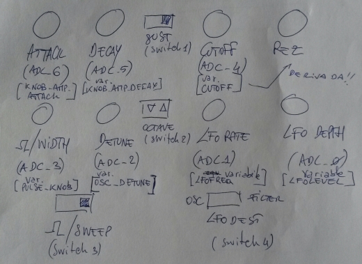
In this hand-made drawing you can see the Anode panel with the names of global variables tied to pots and to switches.

20160725_073555-1

Under each switch you can see the switch number to refer in the code. Under each potentiomenter (in the [] parentheses) you can see the name of the variables used to memorize the pot values.

Note that the pot on the bottom-left is used for two purposes (waveform and width), depending on the position of switch 3. The real variable names for this pot are the following (I know, the drawing is not updated to the last revision of my code…. but I loved to report it in my post 😉  ): WAVETABLE and PULSE_KNOB_LIMITED.

So in the code I managed this in order to display the right values depending on the siwtch position. You can see in file LCD.inc at the labels DISPLAY_WAVETABLE_VAL and DISPLAY_SWEEP_VAL. The choice of the path is done at lines 301 to 303, analyzing the current (and saved in a temporary variable) position of the switch 3.

The other variables names to display reported in the drawing should be OK…. I hope! In any case you can refer to the code, which ever says the truth! 🙂

Integration with Meeblip original code

I included the file LCD.inc after the inclusion of file “subroutines.inc”.

I defined some variable in variable_definition.inc:

///ML 20x4 lcd strings (4 rows of 20 chars+'\0')
my_LCDstring4: .byte 21
my_LCDstring3: .byte 21
my_LCDstring2: .byte 21
my_LCDstring1: .byte 21

//ML temporary variable in RAM
temp_in_RAM: .byte 1

After this, in the main program, the LCD is initialized using:

rcall LCD_START
//---start delay routine
push r18
push r19
push r20
; Generated by delay loop calculator
; at http://www.bretmulvey.com/avrdelay.html
;
; Delay 8 000 000 cycles
; 500ms at 16.0 MHz

    ldi  r18, 41
    ldi  r19, 150
    ldi  r20, 128
L1: dec  r20
    brne L1
    dec  r19
    brne L1
    dec  r18
    brne L1

pop r20
pop r19
pop r18
//----end wait routine---
rcall MYLCD_CLEAR
//prepare LCD gui (not to be refreshed at each basic cycle!)
rcall MYLCD_PREPARE_GUI

Then, the display refresh routine is called at each cpu cycle using:

rcall MYLCD_UPDATE

Note that, since the memory occupation has been increased, I had modified  some “rcall” instruction in “call”. You will find these changes searching for this comment:

//ML--->>changed rcall in call to avoid error " relative branch out of reach"

Well, that’s (mainly all)!

Recompiling the code and burning the binary on the ATMEGA32P you should obtain (after a screen reporting the name and the version of the synth) something like this:

20160719_191421

I’m sorry for the bad picture…but I was so excited! 🙂

The tests using the synth have been all successful, that is:

  • MIDI IN is OK (no MIDI note is lost during play)
  • Audio is OK (the notes produced with the working display have the same waveforms of them produced by the original Meeblip Anode firmware, I tested it with oscilloscope)
  • The interaction with the pots and switches are OK (the refresh of values on the display is very fast respect to the actions on the pots and switches).

So…it seems that a refresh rate of 100 milliseconds should be a good choice for ATMEGA32P computational load!

This is my MeeBlip Anode “Italian Way”, and now, after this great ordeal, I am ready for a (big) glass of Italian grappa. 🙂

I recall here the link to the code in GitHub: https://github.com/garretlabs/meeblip-anode/tree/meeblip_anode_italian_way

…Bonus Easter Egg (for die-hard geeks only): overclock it!

I am an old style geek… some years ago one of my hobbies was to overclock the CPUs of my computers.

I know that ATMEGA32P can be connected to a crystal with maximum frequency of 16Mhz (following the datasheet). But…I love the risk (hmmmm…. only on electronics things! 😉 ) so I wanted to connect him to a 20Mhz crystal.

With some basic code modification, you can have your overclocked Meeblip Anode “Italian Way”.

These are the modifications.

Firstly in the anode.asm file we change the cpu frequency:

.SET cpu_frequency = 20000000 //ML changed the CPU frequncy to 20Mhz

The other basic modification is the Timer 0  initilization (which is the hearth of the MeeBlip sound generation):

;initialize Timer0:

      //ldi     r16, 49             ;\  ; Set sample rate to 40.00 kHz //ML---> commented, since we need a new prescaler value
      ldi     r16, 62                ;\  ; Set sample rate to 40.00 kHz: ML---> we use 62 if the clock is 20Mhz since 16Mhz:49=20Mhz:x... in this case we have always the note in tune!
      out     OCr0, r16           ;/ OCr0 = 49 (///ML---> 62 on overclocked version) gives 40000.00 Hz sample rate at 400 cycles per sample loop.
      ldi     r16, 0x0A           ;\ clear timer on compare,
      out     TCCr0, r16          ;/ set prescaler = CK/8

Note that I used the value 62 for r16, instead of theoretically correct value 61, since I used a software tuner to have the best sound (Tunafish for MacOSX) and trying the values around 61.
Then I add a warning also in the initialization of Timer 2 PWM controlling cutoff…

ldi      r16, 0b01100001     ; Phase correct PWM, no prescaler ///ML WARNING: verify if the soud is nice with 20Mhz clock, else adjust!!!

For me the sound is nice…. 😉

In the LCD.inc file you should finally set the new frequency:

.equ    fclk      = 20000000      ;///ML---->new  system clock frequency (for delays)

This should be all for this easter egg… but I think you should do many other improvements of the code!

I had no problem and I played (and I’m playing) with great satisfaction the overclocked synth in my home studio for several projects…. but note that nothing is guaranteed with this mod. So handle with care! 😀


Phhhhhheeeeewww (I can rebreath now :-D)….Well geek boys & girls, that’s really all for this time.

It was a long time without a post on Garretlabs, but with this one I think I paid my debt with DIY community and to Garretlabs readers!

Bye bye folks… and keep always in touch with Garretlabs!

RasPI-Surv: a Raspberry-based scalable SMS remote controlled video surveillance system

Good morning dear security systems fanatics Garretlabs fans!

Today you will be very interested in my new post, I’m sure.

Because today we talk about a high-scalable videosurveillance system called RasPI-Surv, based on:

  • A system controller based on Raspberry PI
  • A practical (and modifications-friendly) command/telemetry interface via SMS messages, using the very well known SIM-900 module from ITEAD.
  • A set of wireless video cameras with good motion detection feature
  • A internet router/modem with wireless access point
  • A Google Mail account (it will be your “house account”), to be accessed via IMAP.

I engineered this system after a very strange request from one of my strangest friends. 🙂

He was looking for a “internal” videosurveillance system with motion detection to be used only during his vacation periods…and after the vacation periods he wanted to disable the system and put all cameras and controller inside a box! 😉

In other words he wanted a “portable” internal video surveillance system, without in-the-wall connections, without fixed positions for the cameras, so a very dynamic system with the opportunity to move the cameras and the controller inside his house. Plus, he wanted a powerful and portable alarm siren to be placed in his house, without external components (please note that this DIY solution is not accepted by italian laws, so in our country the alarm device must be always placed by a devoted an credited technician).

A practical example of the siren 12V powered could be THIS  …but you can buy another model following your needs.

Thinking for a smart solution, I studied a system with two day-night wireless IP Cameras from HooToo with pan and tilt features (http://www.hootoo.com/hootoo-ht-ip211hdp-indoor-wireless-network-camera-with-ir-cut-black.html) and two day-night D-Link fixed cameras (http://www.dlink.com/it/it/home-solutions/view/network-cameras/dcs-932l-day-night-cloud-camera). But you could add/remove wireless IP cameras with motion detection featire (also of different brands), in order to add/remove “eyes” to your system.

So, this is a very scalable solution. 😉

Firstly I placed the cameras near a wall power socket (ok, they are wireless..but unfortunately they need power… 😦 ), then I connected all cameras to the internet modem/router following their own user guides.

Finally I enabled their motion detection feature with the email sending (using the “house Google Mail account”) of the captured frame when a motion is detected.

Note that for some camera, a fast tramsition from day to night vision and viceversa (i.e. a sun ray refled by a passing car in the street) could be recognized as motion (so as a false alarm by the system 😦 )…so the best way to place the camera is in front of closed external doors without glasses and of closed windows with the rolling shutter completely closed.

Well… do you placed the alarm siren and cameras? Have you configured your cameras in order to connect to your modem/router and to send an email using your Google mail account when a motion is detected? Very well… we can go ahead with the system idea.

This is the overview schema of the system (as always drawn by hand by me, sorry for the bad photo! 😉 ):

wpid-2014-11-10-08.37.09.jpg.jpeg

…In practice at this moment we have all cameras connected to our modem/router and a alarm siren connected to the power thru a relay commanded by the Raspberry PI. So, we must to setup the Raspberry PI in order to execute the following operations/requirements:

  • Periodically it should check the SENT folder of your Google Mail account, in order to verify if one of your IP cameras detected one motion (and so they sent an email using your “home account”). The cycle should be fast because one burglar can be very fast to open a window and to move in your house… 😦
  • If one or more email arrived from your cameras, it should activate the relay in order to power ON the alarm siren
  • In this case it shoud send an SMS to your mobile phone in order to advise you that the siren has been powered ON
  • It should manage a set of SMS commands in order to: force the power OFF of the alarm siren, enable and disable the check of the sent emails, cancel the SMS memory of the SIM900 module, reset or reboot the system etc.
  • It should send a set of SMS in order to advise you that there is some problem (i.e. the internet connection is down, so the Google Mail mailbox can’t be accessed).

Well. It is’nt so difficult to implement it all. If you you read first these previous posts from Garretlabs: THIS ONE (it uses a GSM dongle and the software gammu in order to receive/send the SMS messages, plus to command the GPIO pins of Raspberry using Python) and also THIS ONE (it uses the SIM900 module and the AT commands in order to receive/send the SMS messages).

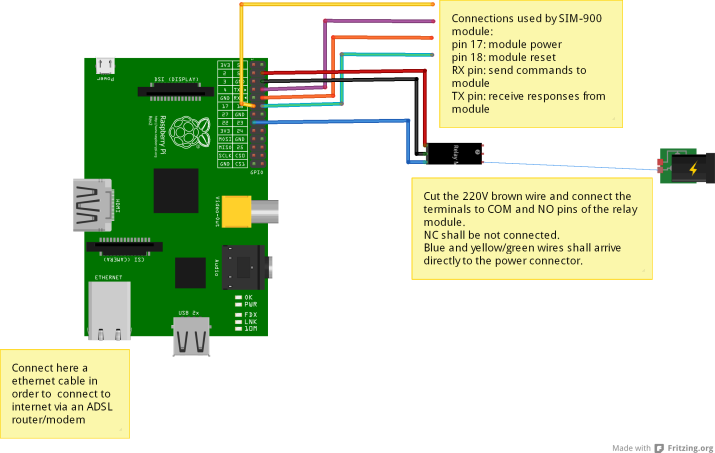
This is the Fritzing schema of the controller Raspberry PI+SIM900 module used to command the relay for the alarm siren:

Video surveillance controller (finale per uso con SIM900) v2_bb

I propose you the complete code of my project…. so you can now start playing with the RasPI-Surv system


#! /usr/bin/env python

import RPi.GPIO as GPIO
import imaplib, re, time, serial, subprocess

#class from http://segfault.in/2010/07/playing-with-python-and-gmail-part-1/ and http://segfault.in/2010/08/playing-with-python-and-gmail-part-2/
class pygmail(object):
    def __init__(self):
        self.IMAP_SERVER='imap.gmail.com'
        self.IMAP_PORT=993
        self.M = None
        self.response = None
        self.mailboxes = []

    def login(self, username, password):
        self.M = imaplib.IMAP4_SSL(self.IMAP_SERVER, self.IMAP_PORT)
        rc, self.response = self.M.login(username, password)
        return rc

    def get_mailboxes(self):
        rc, self.response = self.M.list()
        for item in self.response:
            self.mailboxes.append(item.split()[-1])
        return rc

    def get_mail_count(self, folder='Inbox'):
        rc, self.response = self.M.select(folder)
        return self.response[0]

    def get_unread_count(self, folder='Inbox'):
        rc, self.response = self.M.status(folder, "(UNSEEN)")
        unreadCount = re.search("UNSEEN (\d+)", self.response[0]).group(1)
        return unreadCount

    def get_imap_quota(self):
        quotaStr = self.M.getquotaroot("Inbox")[1][1][0]
        r = re.compile('\d+').findall(quotaStr)
        if r == []:
            r.append(0)
            r.append(0)
        return float(r[1])/1024, float(r[0])/1024

    def get_mails_from(self, uid, folder='Inbox'):
        status, count = self.M.select(folder, readonly=1)
        status, response = self.M.search(None, 'FROM', uid)
        email_ids = [e_id for e_id in response[0].split()]
        return email_ids

    def get_mail_from_id(self, id):
        status, response = self.M.fetch(id, '(body[header.fields (subject)])')
        return response

    def rename_mailbox(self, oldmailbox, newmailbox):
        rc, self.response = self.M.rename(oldmailbox, newmailbox)
        return rc

    def create_mailbox(self, mailbox):
        rc, self.response = self.M.create(mailbox)
        return rc

    def delete_mailbox(self, mailbox):
        rc, self.response = self.M.delete(mailbox)
        return rc

    def logout(self):
        self.M.logout()

#end library/class

##############################################################################
#Functions to PowerON OFF the relay
##############################################################################
#poweron the relay
def PowerONRelay():
    GPIO.setup(22,GPIO.OUT);
    GPIO.output(22,GPIO.HIGH);
    return;

#poweroff the relay
def PowerOFFRelay():
    GPIO.setup(22,GPIO.OUT);
    GPIO.output(22,GPIO.LOW);
    return;

##############################################################################
#Functions to manage SMS
##############################################################################
#check unread arrived messages
def CheckNewUnreadMessage(ser):
    print "Check for new messages..\n";
    ser.write("at\r");
    time.sleep(3);
    line=ser.read(size=64);
    #print line;
    ser.write('AT+CMGL="REC UNREAD"\r')
    time.sleep(3);
    response=ser.read(size=200);
    print response;
    return response;

#function to send confirmation SMS
def SendSMS(ser,value):
    #send SMS about the action
    ser.write("at\r");
    time.sleep(3);
    line=ser.read(size=64);
    print line;
    ser.write('AT+CMGS="+391234567890"\r'); #here put your phone number :-)
    time.sleep(3);
    if (value==1):
        ser.write('ALARM ON!\r');
    elif (value==0):
        ser.write('ALARM OFF!\r');
    elif (value==3):
        ser.write('ALARM enabled!\r');
    elif (value==4):
        ser.write('ALARM disabled!\r');
    elif (value==11):
        ser.write('ALARM commanded OFF (was ON)!\r');
    elif (value==20):
      ser.write('Deleted SIM memory!\r');
        elif (value==50):
      ser.write('INTERNET DOWN!\r');
    elif (value==51):
      ser.write('INTERNET UP!\r');
    elif (value==60):
      ser.write('Warning: GMAIL temporary DOWN!\r');
    time.sleep(3);
    ser.write(chr(26));
    return;

#function to delete messages...(GSM900 stores only 30 messages..)
def DeleteAllMsg(ser):
    ser.write("at\r");
    time.sleep(3);
    line=ser.read(size=64);
    print line;
    print "Deleting memory....";
    ser.write('AT+CMGD=1,4\r');
    time.sleep(3);
    return;    

###############################################################################
#main program for alarm check
###############################################################################
#global variables
initials_sent_emails=0
ALARM_enabled=True
ALARM_ON=False
actual_sent_emails=0;
ALARM_ON_cycles=0;
INTERNET_UP=True;
GMAIL_UP=True;
################################################################################
#functions to enable/disable/stop alarm (sent VIA SMS)
################################################################################
def enable_ALARM():
         global ALARM_enabled
         ALARM_enabled=True
         

def disable_ALARM():
         global ALARM_enabled
         ALARM_enabled=False
         

def stop_ALARM():
        global initials_sent_emails
        global actual_sent_emails
        #ALARM_ON=False
        initials_sent_emails=actual_sent_emails
        #ALARM_ON_cycles=0
        #TODO here send SMS telemetry

################################################################################
#MAIN program
################################################################################

#0: power ON the SIM900 module and waits for SIM registration
GPIO.setmode(GPIO.BCM)
GPIO.setup(17,GPIO.OUT)
GPIO.output(17,GPIO.HIGH)
print "Registering the sim...\n";
time.sleep(15); #wait for sim to register to the net
#0a: open serial link on /dev/ttyAMA0. It is open only one time:it remains open for all operation time.
#No more open+close action is now requested.
print "Opening communications serial...\n";
ser=serial.Serial('/dev/ttyAMA0',9600,timeout=1);
ser.open();


#1: first login to Gmail
g = pygmail()
g.login('your.home.mailbox@gmail.com', 'yourpassword')
print g.response

#2: list mailboxes
g.get_mailboxes()
for item in g.mailboxes:
  print item

#3: get number of sent emails at power ON of alarm controller...
g.get_mail_count('[Gmail]/Posta inviata')
print g.response
sent_number=g.response[0]
initials_sent_emails=int(sent_number) #actual number of sent messages
print initials_sent_emails

#4:logout from gmail
g.logout();


#Here we add the infinite loop (once per 10 seconds?) which:
#a. checks the number of sent emails (login+get_mails_count+logout)
#b. if the number is > initials_sent_emails sets (&& the alarm is ARMED) the alarm relay ON, else sets the alarm relay OFF
#b2. if this is the first time the alarm is ON, send SMS to communicate the ALARM is correctly ON!
#c. checks if a NEW SMS is arrived in order to enable/disable ALARM relay, and update the global variable
#d: waits for 10 seconds (TBC)
while (True):

       #a0: check for internet status
    ip="www.google.it";
        ret=subprocess.call("ping -c 1 %s" %ip,
        shell=True,
        stdout=open('/dev/null','w'),
        stderr=subprocess.STDOUT)
    if (ret==0):
         print "INTERNET UP!"
        if(INTERNET_UP==False):
            INTERNET_UP=True;
            SendSMS(ser, 51);
    else:
        print "INTERNET DOWN!"
        if (INTERNET_UP==True):
            INTERNET_UP=False;
            SendSMS(ser, 50);

    
       #a: check new sent messages
    if (INTERNET_UP==True):
            print 'Check new sent messages...'
        try:
                g.login('your.home.mailbox@gmail.com', 'yourpassword')
                g.get_mail_count('[Gmail]/Posta inviata')
                actual_sent_emails=int(g.response[0])
                g.logout();
            GMAIL_UP=True
        except imaplib.IMAP4.error, err:
            print 'GMAIL IMAP temporary unavailable!!!'
            if (GMAIL_UP==True):#the first time it sends an sms...
                SendSMS(ser,60)
                GMAIL_UP=False        

        #b/b2: alarm management
        print 'Alarm management...'
        if(ALARM_enabled==1 and actual_sent_emails>initials_sent_emails):
                print 'ALARM ON!!!'
                ALARM_ON=True
                ALARM_ON_cycles=ALARM_ON_cycles+1;
                #here we command the relay ON
                PowerONRelay();
                if (ALARM_ON_cycles==1):
                        SendSMS(ser,1);
                
        else:
                if(ALARM_ON==True):
                        SendSMS(ser,0); #if the alarm is already OFF, dont send messages...
                ALARM_ON=False
                ALARM_ON_cycles=0;
                #here we command the relay OFF
                PowerOFFRelay();
                print 'ALARM OFF!'

        #c: new SMS arrived management
        print 'SMS management'
    message=CheckNewUnreadMessage(ser);
    if(message.find("enablealarm")<>-1):
        enable_ALARM();
        #send message to my phone that Relay is ON
            SendSMS(ser, 3);
        print "Alarm enabled commanded\n";    
    elif (message.find("disablealarm")<>-1):
        disable_ALARM();
        SendSMS(ser, 4);
        print "Alarm disabled commanded\n";
    elif (message.find("alarmoff")<>-1):
        stop_ALARM();
        #send message to my phone that telemetries are OFF
          SendSMS(ser, 11);
        print "Deactivated alarm\n";
        elif (message.find("delsms")<>-1):
        DeleteAllMsg(ser);
        SendSMS(ser,20);

       
        #d: basic cycle time
        print 'Wait for new cycle...'
        time.sleep(2);


Weeeeeeell….I Hope the code is well commented,so it is not so unreadable! 😉

As you see, I used a very nice Python library in order to connect to Google Mail using IMAP. You can download it from Segfault.in, and you can find good examples in the following pages: http://segfault.in/2010/07/playing-with-python-and-gmail-part-1/  and http://segfault.in/2010/08/playing-with-python-and-gmail-part-2/.

…Anyway, if you want to request some detail…I am here for you! 🙂

And as usual, if you want to comment/modify/correct/redistribute/relink my code and my idea, you ‘re free to do it (…and thanks for the your pingbacks and for credits in your blogs etc. 😉 )!

Bye bye geek guys and girls… it’s time for me to go to install and test the system in my friend’s house (also if it’s too late for his vacation time..ah ah!!!)! 🙂


…and now ANOTHER music post: SparkPunk Sequencer MIDI synchronisation with Arduino (work in progress)

“Tunz-tunz-tunz” 😀 my dear geek-musician friends (female and male of course)!

Today I used for you my “house-disco-techno”-style “hello”, because today I wan t to talk you about msuica (again).

Some day ago I bought from my preferred store (RobotItaly, as you know), and I assembled two new exciting toys from Sparkfun: Sparkpunk Sound Generator and SparkPunk Sequencer.

The Sparkpunk Sound generator is a very interesting sound generator similar to the famous ATARI Punk Console,  The Sparkpunk Sequencer is a control voltage step sequencer used to control the the Sound Generator.

After the assembly of the two devices, I played some hour with these objects… but, as you know, I am a (pro-am) musician, and I would like to have a MIDI IN  port in all my instruments. Because I attach my devices to my DAW (digital audio workstation, examples are: Steinberg Cubase, Ableton Live, Cakewalk Sonar, Apple Logic Pro etc.) resident on my computers (Mac or PCs), and my DAW  is ALWAYS the MIDI master for my set of instruments. I should command the tempo, the start and stop of my devices.

Before to do my modifications, I printed (and read) the following IMPORTANT page: https://learn.sparkfun.com/tutorials/sparkpunk-sequencer-theory-and-applications-guide . So, firstly I followed the steps for modifications in the section “Synchronizing Multiple Sequencers” and I opened the connections between IN and OUT for the pins CLK, BTN, RUN, STOP (and I used jumpers in order to re-close them again, in case the sequencer isn’t controlled from another device and it used stand alone).

After this, I thinked to use an Arduino UNO as interface between my MIDI master (the DAW) and the Sparkpunk Sequencer in order to force the Sparkpunk Sequencer to follow the MIDI clock of the DAW. This is the actual setup of my experiment:

wpid-20141021_071110.jpg

Well, the PC (Midi OUT port) to Arduino (MIDI IN port) is not difficult: it’s a very simple circuit described in one of my old posts. Using this setup the MIDI in signal pin will be connected to the Arduino D10 pin via SoftSerial.

In order to build logicaly and electrically the interface between Arduino and the SparkPunk Sequencer I studied the signals on the CLK IN, BTN IN, RUN IN, STOP IN pins in the Sequencer stand-alone configuration (so the CLK IN is connected to CLK OUT, BTN IN is connected to BTN OUT, RUN IN is connected to RUN OUT and STOP IN is connected to STOP OUT… using my preferred tools: the jumpers!).

I studied them connectinfg the oscilloscope on the pins and pressing the Run button on the Sequencer in order to start and stop the sequence. These are the results (drawn by hand… it’s so stylish and vintage! 🙂 ):

wpid-storageemulated0DCIMCamera2014-10-21-07.58.15.png.pngWell… as you see the behavior is very simple. And we can simply replicate it using Arduino with the following logic:

  • When Arduino receives from DAW the MIDI START message it commands the RUN IN pin high, the STOP IN pin  low and BTN IN pin firstly high and after a short delay (I used 5ms and it works…but you can measure the real value with the oscilloscope if you want) it commands it again low.
  • When Arduino receives from DAW the MIDI STOP message it commands the RUN IN pin low, the STOP IN pin high and BTN IN pin firstly high and after a short delay (I used 5ms and it works…but you can measure the real value with the oscilloscope if you want) it commands it again low.
  • The CLK IN value is commanded by Arduino following the reception of the MIDI CLK message, in order to synchronize the tempo of Sparkpunk Sequencer with the DAW tempo.

IMPORTANT Note: a standard MIDI CLK message is sent by a DAW 24 times per quarter note. A time of 120 BPM (beats per minute) is equivalent to 120 quarter notes per minute, so in this case the DAW sends from the MIDI out (120*24)/60 messages per second. It’s too much for our Sparkpunk sequencer (if you sends all these messages to ther sequencer, it doesn’t work…and you can’t see the ON/OFF of the Rate led).

So I decided to send to the SparkPunk sequencer only one MIDI CLK message per 24 received by the MIDI IN port on Arduino. In other words Arduino decreases the rate of MIDI CLK message in order to correctly command the sequencer.

Regarding the hardware connections, the are very simple:

  • Connect the Arduino GND to a GND point of the Sparkpunk system (i.e. the ground of the Speaker port on the Sound Generator)
  • Connect the Arduino pin D2 to the RUN IN of Sparkpunk sequencer
  • Connect the Arduino pin D3 to the STOP IN of Sparkpunk sequencer
  • Connect the Arduino pin D4 to the CLK IN of Sparkpunk sequencer
  • Connect the Arduino pin D5 to the BTN IN of Sparkpunk sequencer

This is the simple Arduino code:

#include <SoftwareSerial.h>
SoftwareSerial MidiSerial(10, 11); // RX, TX

byte midi_start = 0xfa; 
byte midi_stop = 0xfc; 
byte midi_clock = 0xf8; 
byte midi_continue = 0xfb; 
int play_flag = 0;
byte data;

//synchro values
int number_of_received_clocks=0;

#define MAX_BPM 160
#define MIN_BPM 20

void setup() 
{ 
  MidiSerial.begin(31250); 
  Serial.begin(115200);
  //led 13 used for debug
  pinMode(13, OUTPUT);
  digitalWrite(13, LOW);
 
  //interface --->Sparkpunk sequencer
  pinMode(2,OUTPUT);
  digitalWrite(2,LOW); //midi start sequencer
  
  //interface --->Sparkpunk sequencer
  pinMode(4,OUTPUT);
  digitalWrite(4,LOW); //midi synch sequencer
  
  //interface --->Sparkpunk sequencer
  pinMode(3,OUTPUT);
  digitalWrite(3,HIGH); //midi stop sequencer
  
  //interface --->Sparkpunk sequencer
  pinMode(5,OUTPUT);
  digitalWrite(5,LOW); //button sequencer 
}

void loop() 
{
  if(MidiSerial.available() > 0) 
  {
    data = MidiSerial.read();
     if(data == midi_start) {
       Serial.println("Start Midi");
       
       //sparkpunk interface commands
       digitalWrite(2,HIGH);//start/run sequencer
       digitalWrite(3,LOW);//stop sequencer
       digitalWrite(5,HIGH);//button sequencer
       delay(10);
       digitalWrite(5,LOW);//button sequencer
       
       play_flag = 1;
      }
      else if(data == midi_continue) 
      {
        play_flag = 1;
      }
      else if(data == midi_stop) {
        Serial.println("Stop Midi");
       
       digitalWrite(2,LOW);//start/run sequencer
       digitalWrite(3,HIGH);//stop sequencer
       digitalWrite(5,HIGH);//button sequencer
       delay(10);
       digitalWrite(5,LOW);//button sequencer
       
        play_flag = 0;
        number_of_received_clocks=0;
      }
      else if((data == midi_clock) && (play_flag == 1)) { 
        number_of_received_clocks++;
        //Serial.println(number_of_received_clocks);
        if(number_of_received_clocks%24==0) //see MIDI specification: the clock is sent 24 times for quarter note, and 120BMP=120 quarter notes for minute => BPM value= 60/time to receive 24 clocks
          {
            Sync();
          }
      } 
  }
}

void Sync() {
     digitalWrite(4, HIGH);
     delay(100); //high part of the clock square wave.
     digitalWrite(4, LOW);
}

As you see I used for the CLK IN  a square wave with a period of 200 ms (100 ms high and 100 ms low). It seems sufficient in order to command the step ahead of the sequence.

Ok, using this sketch and starting the MIDI clock on my DAW, the Sparkpunk Sequencer starts working, exactly synchronized with the DAW (and the sound is correctly generated by the Sound Generator). Modifying the BPM tempo on the DAW causes that Sparkpunk SEquencer changes correctly his tempo, and it correctly starts/stopswhen the start/stop command is sent by the DAW. Yeahhhhhhhhh! 😉

But.

Yes, there are always some “But” in my projects. 🙂

In this case there are still some strange behaviors of the system, to be investigated and debugged (also with YOUR contribution, my dear followers, if you want):

  1.  The Sequencer start working also if the POWER switch is OFF, and at the same time the . It’s clear that the sequencer and sound module takes power from the 4 pins connected to Arduino…
  2. In this condition the ouput volume of the Sound Generator is a little low… maybe the Arduino doesn’t drive the correct power supply to all the system. 😦
  3. In this condition (POWER switched OFF) only the LONG pulse works, if I switch on SHORT no sound is emitted from the Sound Generator.
  4. If I change the POWER switch from OFF to ON on the sequencer (or on the Sound Generator), only the SHORT pulse is emitted (if I switch to LONG pulse no sound is emitted)
  5. Finally, in this case (POWER switched ON on the Sequencer) the output volume of the Sound Genrator is higher.

I think all is tied to the fact that Arduino power is not sufficient to drive all the circuits (Arduino itself+MIDI interface, Sound Generator and Sequencer), and to the fact that Arduino uses 5V as HIGH value for the CLK IN, but Sparkpunk sequencer uses 7.5V. See also the paragraph called “Switch Voltage Processing” in the  https://learn.sparkfun.com/tutorials/sparkpunk-sequencer-theory-and-applications-guide …I think it is very involved in this behavior of the circuit. I’m continuing my investigation.

Another solution I would try in the near step of my experiment is to use a MOSFET commanded by Arduino pin D5 (connecting the D5 to the gate pin, the CLK IN to the source pin and the CLOCK OUT to the drain pin, for example), in order to control the synch pulse on the CLK IN connecting it to the CLK OUT (something similar to a electronic switch), in order to have the same situation of the stand alone Sequencer configuration, but generating the clock pulses using the MIDI tempo. It’s a solution similar to which used in this video from Sparkfun: https://www.youtube.com/watch?v=LUcqDM4k1gU

Well… but now, after this ordeal, I’m really ready for a glass (…a bottle?) of my preferred grappa. If you know what I mean. 😉

Bye bye daft-punk-electronicmusicians-techno friends!


Thermostat with Arduino and touchscreen

..Hi, dear techno frieds (obviously male and female)!
My holidays unfortunately ended some day ago, and now it’s time to restart the work in my garret (and in the Garretlabs). It seems that your visits to my little blog during August increased…so many many many (many) thanks to you all! 🙂
Once returned from my vacation, my dear friend Luka Cekka (it isn’t his real name, so he isn’t a Russian guy, but a real Italian guy, and he is a “spitting image” of Tim Robbins in “Antitrust”…have you seen the movie? 😉 ) asked to me to realize a thermostat with touch screen for his new house thermo installation.

LukaCekka

My friend Tim Robbins… ehmm Luka Cekka! 😉

So… I realized the first prototype using my old friend Arduino UNO, a temperature and humidity DHT22 sensor and the well known Adafruit TFT 2.8” touchscreen. (http://www.adafruit.com/products/1651). As usual, I bought the touchscreen from Robot Italy, my preferred italian store!
Well, in order to extract the necessary pins for DHT22 and a led (used as alarm monitor for the thermostat), I inserted between Arduino and the TFT screen a cheap proto shield (from Sparkfun) modified and transformed in a very useful “breakout shield”.

Once created the “sandwich” with Arduino, the breakout shield and the TFT, I connected to Arduino the DHT22 and the alarm led on the breadboard.
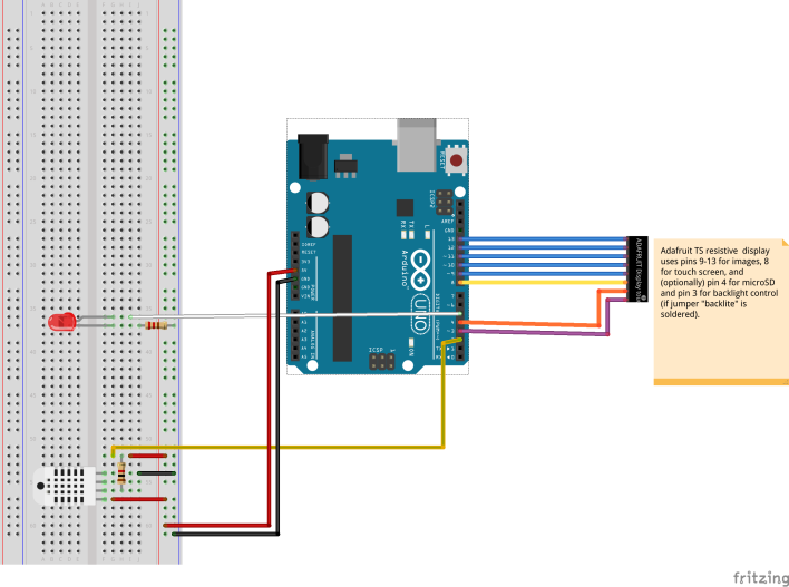
This is the Fritzing diagram (please, see the note and pay attention to the use of Arduino pins in order to drive the Adafruit TFT):

Cekka_controller_v1(one temp sensor)_bb
Regarding the software, I started using the following ad-hoc DHT22 library (and one very useful example found on internet) and verifying that the sensor was OK (and the alarm led ON/FF strategy).
Secondly, I added the code to manage the visualization of the temp on TFT, starting from the well coded examples from Adafruit libraries.
I decided to have two software modes: in the “temps” mode you can see the actual temperature acquired from DHT22. In this mode you can touch the software button “SETUP” on the touchescreen in order to enter “setup” mode. In “setup” mode you can adjust the alarm temperature using two software buttons on the touchscreen (one “+” button and one “-” button). You can return to “temps” mode touching the “TEMPS”software button. …All simple! 😉

This is the complete Arduino code for my application:

#include "DHT.h"
#include <Adafruit_GFX.h>
#include <SPI.h>
#include <Wire.h>
#include <Adafruit_ILI9341.h>
#include <Adafruit_STMPE610.h>

//Adafruit screen data
// This is calibration data for the raw touch data to the screen coordinates
#define TS_MINX 150
#define TS_MINY 130
#define TS_MAXX 3800
#define TS_MAXY 4000

//define screen and touch screen plus control signals
#define STMPE_CS 8
Adafruit_STMPE610 ts = Adafruit_STMPE610(STMPE_CS);
#define TFT_CS 10
#define TFT_DC 9
Adafruit_ILI9341 tft = Adafruit_ILI9341(TFT_CS, TFT_DC);

//temperatures frame
#define FRAME_X_T 80
#define FRAME_Y_T 6
#define FRAME_W_T 150
#define FRAME_H_T 150
//button frame
#define FRAME_X_B 210
#define FRAME_Y_B 180
#define FRAME_W_B 100
#define FRAME_H_B 50

//declare temp sensor
DHT dht;

//declare inital default max temp (setpoint) in order to signal an alarm
float max_temp=27.0;

//display modes--->used to define the menu (in the right-low corner) button text and behaviour
 #define MODE_TEMPS 1
 #define MODE_SETUP 2
 int current_display_mode=MODE_TEMPS;//at startup we see the temps..
 //coords and dimension for the + and - buttons, used to set max temps...
 #define X_PLUS_B 224
 #define X_MINUS_B 270
 #define Y_PLUS_B 3
 #define BUTTON_W 40
 #define BUTTON_H 35

void setup()
 {
   //serial
   Serial.begin(9600);
   Serial.println();
   Serial.println("Status\tHumidity (%)\tTemperature (C)\t(F)");
   //Use pin D2 to read temp/hum from DHT22
   dht.setup(2);
   //set pin D5 to output (alarm pin)
   pinMode(5,OUTPUT);
   
   //initialize touch screen
   tft.begin();
   if (!ts.begin()) {
      Serial.println("Unable to start touchscreen.");
   }
   else {
      Serial.println("Touchscreen started.");
   }
   tft.fillScreen(ILI9341_BLUE);
   // origin = left,top landscape (USB left upper)
   tft.setRotation(1);
   
   //draw button TS
   drawMenuButton(current_display_mode);
 }

void loop()
 {
   //set delay
   delay(dht.getMinimumSamplingPeriod());

   //get values from DHT22
   float humidity = dht.getHumidity();
   float temperature = dht.getTemperature();
   
   //debug: print value on serial
   Serial.print(dht.getStatusString());
   Serial.print("\t");
   Serial.print(humidity, 1);
   Serial.print("\t\t");
   Serial.print(temperature, 1);
   Serial.print("\t\t");
   Serial.println(dht.toFahrenheit(temperature), 1);
   
   //print value on Adafruit screen
   if (current_display_mode==MODE_TEMPS)
   {
      drawFrameT();
      RefreshTemp1Value(temperature);
   }
   else if (current_display_mode==MODE_SETUP)
   {
      //nothing
   }
   
   //Management of max temp in order to activate the alarm (led)
   if (temperature>=max_temp)
   {
      //set HIGH alarm pin (D5)
      digitalWrite(5,HIGH);
   }
   else
   {
      digitalWrite(5,LOW);
   }
 
   //Management of Adafruit touchscreen
   // See if there's any touch data for us
   if (!ts.bufferEmpty())
   {
       // Retrieve a point
       TS_Point p = ts.getPoint();
       // Scale using the calibration #'s
       // and rotate coordinate system
       p.x = map(p.x, TS_MINY, TS_MAXY, 0, tft.height());
       p.y = map(p.y, TS_MINX, TS_MAXX, 0, tft.width());
       int y = tft.height() - p.x;
       int x = p.y;

       //check if the Menu button is pressed
       if((x > FRAME_X_B) && (x < (FRAME_X_B + FRAME_W_B)))
       {
          if ((y > FRAME_Y_B) && (y <= (FRAME_Y_B + FRAME_H_B)))
          {
              if (current_display_mode==MODE_TEMPS)
              {
                  current_display_mode=MODE_SETUP;
                  tft.fillScreen(ILI9341_BLACK);
                  drawMenuButton(current_display_mode);
                  
                  //draw the Temp max set points controls
                  drawCurrentMaxTemp1(max_temp);
              }
              else
              {
                  current_display_mode=MODE_TEMPS;
                  tft.fillScreen(ILI9341_BLUE);
                  drawMenuButton(current_display_mode);
              }
          }
      }

      //check if + or - buttons are pressed and adjust max temp
      if((x > X_PLUS_B) && (x < (X_PLUS_B + 40)))
      {
          if ((y > Y_PLUS_B) && (y <= (Y_PLUS_B + 35)))
          {
             if (current_display_mode==MODE_SETUP)
             {
                max_temp=max_temp+0.5;
                tft.fillRect(6,6,X_PLUS_B-3,Y_PLUS_B+BUTTON_H,ILI9341_BLACK);
                drawCurrentMaxTemp1(max_temp);
             }
          }
      }
      
      if((x > X_MINUS_B) && (x < (X_MINUS_B + 40)))
      {
         if ((y > Y_PLUS_B) && (y <= (Y_PLUS_B + 35)))
         {
            if (current_display_mode==MODE_SETUP)
            {
                max_temp=max_temp-0.5;
                tft.fillRect(6,6,X_PLUS_B-3,Y_PLUS_B+BUTTON_H,ILI9341_BLACK);
                drawCurrentMaxTemp1(max_temp);
            }
         }
      }
   }
 }
 

//Adafruit screen functions
void RefreshTemp1Value(float value)
{
 //drawFrameT1();
 //tft.fillRect(REDBUTTON_X, REDBUTTON_Y, REDBUTTON_W, REDBUTTON_H, ILI9341_BLUE);
 tft.setCursor(6 , 6);
 tft.setTextColor(ILI9341_WHITE);
 tft.setTextSize(4);
 tft.print("T1= ");
 tft.println(value);
}

void drawFrameT()
{
 tft.fillRect(FRAME_X_T, FRAME_Y_T, FRAME_W_T, FRAME_H_T, ILI9341_BLUE);
}

void drawMenuButton(int current_mode)
{
 tft.fillRect(FRAME_X_B, FRAME_Y_B, FRAME_W_B, FRAME_H_B, ILI9341_BLUE);
 tft.drawRect(FRAME_X_B, FRAME_Y_B, FRAME_W_B, FRAME_H_B, ILI9341_BLACK);
 tft.setCursor(FRAME_X_B+ 6 , FRAME_Y_B + 15);
 tft.setTextColor(ILI9341_RED);
 tft.setTextSize(3);
 if (current_mode==MODE_TEMPS)
      tft.println("SETUP");
 else if (current_mode==MODE_SETUP)
      tft.println("TEMPS");
}
void drawCurrentMaxTemp1(float value)
{
 tft.setCursor(6 , 6);
 tft.setTextColor(ILI9341_WHITE);
 tft.setTextSize(3);
 tft.print("MAX T1=");
 tft.println(value);
 drawPlusButton(X_PLUS_B/*224*/,Y_PLUS_B/*3*/);
 drawMinusButton(X_MINUS_B/*270*/,Y_PLUS_B/*3*/);
}

void drawPlusButton(int x, int y)
{
 tft.fillRect(x, y, BUTTON_W, BUTTON_H, ILI9341_BLUE);
 tft.setCursor(x+10 , y+5);
 tft.setTextColor(ILI9341_WHITE);
 tft.setTextSize(4);
 tft.print("+");
}

void drawMinusButton(int x, int y)
{
 tft.fillRect(x, y, BUTTON_W, BUTTON_H, ILI9341_BLUE);
 tft.setCursor(x+10 , y+5);
 tft.setTextColor(ILI9341_WHITE);
 tft.setTextSize(4);
 tft.println("-");
}

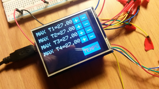
Ok, these are the photos of the complete project.

wpid-storageemulated0DCIMCamera2014-09-15-17.08.25.png.png

wpid-storageemulated0DCIMCamera2014-09-10-06.39.30.png.png

Note that on the screen there are four temperature values: I’m now working on a more powerful application in order to match Luka request (he wants to use four DHT22 sensors in his house… I think I will use a input multiplexer with the Arduino UNO, or more simply an Arduino Mega! 😉 ).
But you can use this project in order to add the powerful Adafruit TFT touchscreen to your application.
Only two notes on the Adafruit TFT:
1. the screen refresh is slow (very slow in my opinion), but it’s an acceptable issue in embedded projects
2. the touchscreen is natively very sensitive to human touch, so if your touch is “too long” it will be detected as a multiple touch. You could implement some “low-pass software filter” (i.e. you could manage the touch only after a multiple touch).

Well boys and girls, now you have a thermostat with a touch screen for your hi-tech house. I hope Luka will be happy with his new toy (but I’m not sure..he is a very perfectionist guy! 😉 ).
…But attention friends, the touchscreen will record your fingerprints ;-), so clean it with attention…especially if you don’t like CSI! 🙂

Bye bye!

The GL holidays post: a multifunction anti-intrusion system using Arduino!

….Thanks God it’s holidays time, my dear geeks! 🙂

Well… during these days it isn’t a good idea to remain in a dark and little microelectronics laboratory, it’s a better solution to close your laboratory in order to go in a good house/hotel by the sea (or at the mountains)! 😉

So, today Garretlabs wants to propose you a very simple (but) all-in one solution of house anti-intrusion alarm system, based on Arduino UNO.

This basic idea is very compact (but you can add all the subsystem you invent/want):

  • we will monitoring a set of house internal doors via a “wired connection”, using the digital in/out Arduino pins in order to detect a door openting (…I confess: this is inspired from a old joke which I knew 😦 during a high school week at the mountains … as we say in Italy literally “White Week” that is “Settimana bianca”)
  • we will also manage a ultrasonic sensor in order to monitoring tha opening of another house internal door
  • in case of door opening detection, we will send an alarm email using the well known Arduino Ethernet Shield

This is, as usual, my hand-made design of the system 🙂 :

2014-07-22 09.17.29

The part list is (as usual) very short, because my goal is to use (when possible) only the parts present at the moment in my …garret! 😉

  • One Arduino UNO
  • One Arduino Ethernet shield
  • One ultrasonic sensor
  • Assorted cables (never too many! ;-))

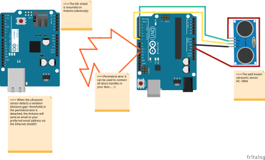
This is the Fritzing circuit (click on the image to see it bigger):

Ultrasonic alarm v1_bb

Well, remember to the Arduino place in a safe and fixed position in the house (for exaple fixed on the roof or fixed inside a electrical box on the wall) because if someone will open one of the doors connected by wire, our goal is that the wire will be disconnected from one of the two used Arduino digital pins (in order to open the controlled signal circuit).

Now, let’s go to code some line. The ultrasonic sensor is managed by the excellent newPing library, and the code to send email using the Arduino Ethernet shield is took from the my preferred site about Arduino resources (the only and one Arduino.cc …”made in Italy” rules! :-)), and modified by myself. The specific link is the following: http://playground.arduino.cc/Code/Email.

So, this is the code.

#include <SPI.h>
#include <Ethernet.h>
#include <NewPing.h>

#define TRIGGER_PIN 6 // Arduino pin tied to trigger pin on the ultrasonic sensor.
#define ECHO_PIN 7 // Arduino pin tied to echo pin on the ultrasonic sensor.
#define MAX_DISTANCE 400 // Maximum distance we want to ping for (in centimeters). Maximum sensor distance is rated at 400-500cm.
NewPing sonar(TRIGGER_PIN, ECHO_PIN, MAX_DISTANCE); // NewPing setup of pins and maximum distance.

// choose the MAC!
byte mac[] = { 0x90, 0xAA, 0xAA, 0x00, 0x59, 0x67 };

// change network settings
IPAddress ip( 192, 168, 0, 30 );
IPAddress gateway( 192, 168, 0, 1 );
IPAddress subnet( 255, 255, 255, 0 );

// change to your server SMTP
char server[] = "out.alice.it"; //note I used my italian ISP provider server to send emails... :-)
EthernetClient client;
unsigned int initial_distance;
bool ULTRASONIC_ALARM_ARMED=true;
bool PERIMETRAL_ALARM_ARMED=true;
void setup()
{   
   //start ehternet and serial
   Serial.begin(9600);
   pinMode(13,OUTPUT);
   digitalWrite(13,HIGH);
   Ethernet.begin(mac, ip, gateway, gateway, subnet);
   delay(2000);
   //calibration of ultrasonic sensor
   Serial.print("Calibrating....");
   for (int i=0;i<100;i++)
   {
      delay(50); // Wait 50ms between pings (about 20 pings/sec). 29ms should be the shortest delay between pings.
      unsigned int uS = sonar.ping(); // Send ping, get ping time in microseconds (uS).
      initial_distance+=uS / US_ROUNDTRIP_CM;
   }
   
   initial_distance=initial_distance/100;
   Serial.print("Initial distance:");
   Serial.print(initial_distance);
   Serial.println("cm");
   digitalWrite(13,LOW);
   //setup the perimetral cable
   pinMode(10,OUTPUT);
   pinMode(11,INPUT);
   digitalWrite(10,HIGH);
}

void loop()
{  
   byte inChar;
   unsigned int distance=0;
   unsigned int medium_distance=0;
   //inChar = Serial.read();
   for (int i=0;i<20;i++)
   {
      delay(50); // Wait 50ms between pings (about 20 pings/sec). 29ms should be the shortest delay between pings.
      unsigned int uS = sonar.ping(); // Send ping, get ping time in microseconds (uS).
      distance+=uS / US_ROUNDTRIP_CM;
   }
   medium_distance=distance/20;
   Serial.print (medium_distance);
   Serial.println (initial_distance);
   if(medium_distance<initial_distance && ULTRASONIC_ALARM_ARMED==true) //note that you can add a threshold in order to reduce false alarms
   { 
      if(sendEmail(1)) Serial.println(F("Email sent"));
      else Serial.println(F("Email failed"));
      ULTRASONIC_ALARM_ARMED=false; //the alarm should send only one email!
   }
   else
   {
      ULTRASONIC_ALARM_ARMED=true; //re-arm the alarm!
   }
   
   if(digitalRead(11)==LOW && PERIMETRAL_ALARM_ARMED)
   {
      if(sendEmail(2)) Serial.println(F("Email sent"));
      else Serial.println(F("Email failed"));
      PERIMETRAL_ALARM_ARMED=false; //the alarm should send only one email per violation!
   }
   else
   {
      //nothing to do: note that the perimetral wire alarm cannot be auto-rearmed! :-(
   }
}

//////////////////////////////////////////////////////////////////////////////
// Send email helper functions.
// Based on: http://playground.arduino.cc/Code/Email
//////////////////////////////////////////////////////////////////////////////

byte sendEmail(int type_alarm)
{
    byte thisByte = 0;
    byte respCode;
    if(client.connect(server,25)) {
        Serial.println(F("connected"));
    } else {
       Serial.println(F("connection failed"));
       return 0;
    }
    if(!eRcv()) return 0;
    Serial.println(F("Sending helo"));
    // change to your public ip
    client.println(F("helo 1.2.3.4"));
    if(!eRcv()) return 0;
    Serial.println(F("Sending From"));
    // change to your email address (sender)
    client.println(F("MAIL From: <your_email@alice.it>"));
    if(!eRcv()) return 0;

    // change to recipient address
    Serial.println(F("Sending To"));
    client.println(F("RCPT To: <your_recipient_address@your_provider.com>"));

    if(!eRcv()) return 0;
    Serial.println(F("Sending DATA"));
    client.println(F("DATA"));
    if(!eRcv()) return 0;
    Serial.println(F("Sending email"));
    // change to recipient address
   client.println(F("To: You <your_recipient_address@your_provider.com>"));

   // change to your address
   client.println(F("From: Me <your_email@alice.it>"));
   if(type_alarm==1) //ultrasonic alarm type
   {
      client.println(F("Subject: Arduino Ultrasonic alarm!\r\n"));
     client.println(F("The Arduino Ultrasonic alarm has been powered ON!"));
   }
   else if (type_alarm==2) //perimetral alarm type
   {
      client.println(F("Subject: Arduino Perimetral alarm!\r\n"));
      client.println(F("The Arduino Perimetral alarm has been powered ON!"));
   }
   client.println(F("."));
   if(!eRcv()) return 0;
   Serial.println(F("Sending QUIT"));
   client.println(F("QUIT"));
   if(!eRcv()) return 0;
   client.stop();
   Serial.println(F("disconnected"));
   return 1;
}

byte eRcv()
{
   byte respCode;
   byte thisByte;
   int loopCount = 0;
   while(!client.available()) {
      delay(1);
      loopCount++;
      // if nothing received for 10 seconds, timeout
      if(loopCount > 10000) {
          client.stop();
          Serial.println(F("\r\nTimeout"));
          return 0;
        }
     }
   respCode = client.peek();
   while(client.available())
   {
      thisByte = client.read();
      Serial.write(thisByte);
   }
   if(respCode >= '4')
   {
      efail();
      return 0;
   }
   return 1;
}

void efail()
{
   byte thisByte = 0;
   int loopCount = 0;
   client.println(F("QUIT"));
   while(!client.available()) {
      delay(1);
      loopCount++;
      // if nothing received for 10 seconds, timeout
      if(loopCount > 10000) {
          client.stop();
          Serial.println(F("\r\nTimeout"));
          return;
      }
   }

   while(client.available())
   {
      thisByte = client.read();
      Serial.write(thisByte);
   }
   client.stop();
   Serial.println(F("disconnected"));
}

Note that I used a SMTP email server which donesn’t use SSL access. In this case the SMTP sender library doesn’t work properly.

Well.. it’s very hot in Florence. I need a cold drink and a visit to a near pool. So, I think I will shutdown my computer now.;-)

But first…I hope you will have good vacation boys and girls. Your microelectronics worm should need a little time of relax, so see you soon at the end of August with other new open source ideas!


MIDin: a trasmitter/receiver sytem for MIDI messages using XBee and Arduino

Hi hi-tech friends (…with a prominent geek attitude 🙂 )!

This time I would like to talk about…MUSIC! Ta-daaaa!!

As you know I am also a musician, and I produce freely downloadable music from my music website www.marcolastri.net (only italian language, sorry!  ).

I have a large set of keyboards and synthesizers in my studio, and I have also a Roland AX-7, a “wearable” MIDI controller keyboard similar to a guitar (today these instruments are called “keytars” 😉 ). This keytar is used also by the mighty Herbie Hancock…. 😉

This keytar has also a great feature: it can be power by 6 AA batteries….but you will have always the midi cable in order to command your sound generator or expander (or software synth etc.). The midi cable is a limitation to your performance freedom on stage…so I want to cut it! 😉

There are some good wireless solution off-the-shelf, for example the Mid-Air product from M-Audio….and the price is not so low. 😦

…So I want to realize a DIY solution, using two Arduinos UNO, two XBee Shields and two XBee modules: this is the Garretlabs MIDin project! Ta-daaaa!

I bought from my preferred store (www.robot-italy.com) the following components:

Then I connected these components to two Arduino UNO boards in order to realize: one component working as MIDI Receiver-XBee Sender and one component working as MIDI Sender-XBee Receiver.

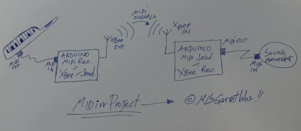
Thi is the system overview…design handmade by ML! 😉

20140711_093503

First step: program the XBee modules

This is the more complex step…I don’t love it but (unfortunately) it is necessary.

We must to setup the Series 2 modules in order to enable the “AT mode” communication (the Series 2 chips support also another -more complicated- configuration, in order to realize very complex networks of XBee modules). In other words, we must to program the devices in order to simulate a point-to-point-connection, a true serial wireless connection.

The best tutorial I’ve found on the internet is the following: http://tutorial.cytron.com.my/2012/03/08/xbee-series-2-point-to-point-communication/comment-page-1/. I used it step-by-step in order to configure my XBee modules…and it worked great! 😉

Firstly I downloaded  and installed the X-CTU utility (only for Windows… 😦 ) from Digi site.

After this, I attached a wire to the RESET pin of the Arduino and I connected it to GND. Then I connected the XBee Shield with the XBee module onboard (remember to set his jumper on “USB”): this is the way to directly access the XBee modules for programming them using Arduino board USB connection. In other words, to program the XBee modules it’necessary to disable the ATMEGA chip, so…or you remove it, or you connect to GND the RST Arduino pin. 😉

So, I used as network ID the suggested number (1234), then I configured one module as Coordinator AT (setting in the values SH/SL of  serial number of Router module), and I configured the other module as Router AT (setting in the values SH/SL of Serial Number of Coordinator module).

Well, once configured, the two modules start to “talk” each other, and the leds on shields start to blink. To test the correct configuration you can use the procedure well explained in the  http://tutorial.cytron.com.my/2012/03/08/xbee-series-2-point-to-point-communication/comment-page-1/.

IMPORTANT NOTE: I used the default speed of serial connection (9600 bps) for XBee modules, since I noticed that if I change the data speed, the USB connection from Arduino IDE to Arduino in order to download applications should fatally fail.


Second step: the MIDI receiver-XBee sender

The difficult step is passed…so, one moment of relax now! 😉

Ok, let’s start with the secdond step.

This MIDI receiver/XBee Sender has one MIDI connector in order to receive MIDI signals from a synthesizer, the software collect them, then it uses the XBee serial link to send MIDI signals to the other system component (see the third step).

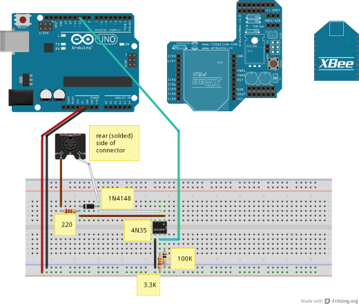
The circuit is very simple…. and it is based on the standard MIDI-IN circuit. See http://www.midi.org/techspecs/electrispec.php to see the details. I modified it a little (especially the optocoupler)…in order to match the parts I had in the “Garret” at the moment 😉 !

The components are:

  • 1x Optocoupler 4N35
  • 1x Diode 4148
  • 1x 100KOhm resistor
  • 1x 220Ohm resistor
  • 1x 3.3KOhm resistor

Note that in the schema I added the XBee module and the XBee shield on the right side of Arduino, in order to better explain the connections, but OBVIOUSLY their must be mounted ON the Arduino! 🙂

XBEE_sender+MIDI_receiver_Garretlabs_bb

The software is simply a MIDI messages collector and re-sender.

Note that I used a buffer to memorize a certain number of MIDI message before to send them, because if wen I receive a message I resend it immediately, I could loose another MIDI message incoming in the meantime. So, I used a “buffering approach”. I verified -as musician 🙂 – that the latency due to buffering is very (very) low, so this approach is acceptable. 😉

Note also that I use the Software Serial (the RX is on pin 10)  to receive MIDI messages, because XBee must use the Serial port.

 #include <SoftwareSerial.h>

SoftwareSerial MidiSerial(10, 11); // RX, TX

byte in_buffer[1024]; //maximum number of bytes arrived in one cpu cycle
unsigned int received_bytes;

void setup()
{
  Serial.begin(9600); //XBEE transmission
  MidiSerial.begin (31250); //MIDI transmission
  
  //led 13 used for debug
  pinMode(13, OUTPUT);
  digitalWrite(13, LOW);
  
  received_bytes=0;

}

void loop()
{
  if(MidiSerial.available()>0)
  {
      received_bytes=MidiSerial.available();
      for (int i=0;i<received_bytes;i++)
        in_buffer[i]=MidiSerial.read();  //save in the buffer all bytes arrived from MIDI port
      
      //write all bytes arrived in the present cycle (so, the input is decoupled from the output)
      digitalWrite(13, HIGH);
      for (int i=0;i<received_bytes;i++)
      {
        Serial.write(in_buffer[i]);
      }
      digitalWrite(13, LOW);
      
      //reset the counter of received bytes in the cycle
      received_bytes=0;
  }
}

In order to write the program on Arduino, you must set the XBee jumper on “USB” position (and obviously you must to remove the cable to ground connected to the RST pin…see step one!). After programming, you should set the jumper on “XBee” position.


Third step: the MIDI sender-XBee receiver

Well, this component is more simple than the previous: it receives the MIDI messages from Xbee serial wireless link and it resend them to the MIDI Out port, in order to command a sound generator, a expander or another synth.

Only one component in this case:

  • 1x 220Ohm resistor

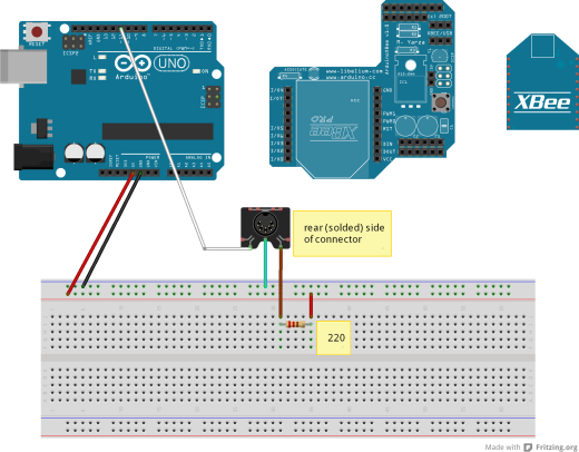
This is the (simple) circuit. As you can note, the MIDI In and Out circuits are NOT mirrored (this is the standard)! ….What a strange design choice!!! 🙂

XBEE_receiver+MIDI_sender_Garretlabs_bb


And this is the Arduino software (the MIDI management functions are taken from http://arduino.cc/en/Tutorial/Midi?from=Tutorial.MIDI):

#include <SoftwareSerial.h>

SoftwareSerial MidiSerial(10, 11); // RX, TX

void setup()
{
  Serial.begin(9600); //XBEE transmission
  MidiSerial.begin (31250); //MIDI transmission
  
  //led 13 used for debug
  pinMode(13, OUTPUT);
  digitalWrite(13, LOW);

}

void loop()
{
  
  if(Serial.available() > 0)
  {
    digitalWrite(13, HIGH);
    MidiSerial.write(Serial.read()); //receives the midi messages via XBEE...and send it to Synth
    digitalWrite(13, LOW);
  }
  //Test function
  //SendAllNotes();
}
////////////////////////////////////////////////////////////////////////////////////////////
//
// MIDI HELPER FUNCTIONS (taken from http://arduino.cc/en/Tutorial/Midi?from=Tutorial.MIDI)
//
////////////////////////////////////////////////////////////////////////////////////////////

void SendAllNotes() {
  // play notes from F#-0 (0x1E) to F#-5 (0x5A):
  for (int note = 0x1E; note < 0x5A; note ++) {
    //Note on channel 1 (0x90), some note value (note), middle velocity (0x45):
    digitalWrite(13, HIGH);
    MIDICommand(0x90, note, 0x45);
    delay(100);
    digitalWrite(13, LOW);
    //Note on channel 1 (0x90), some note value (note), silent velocity (0x00):
    MIDICommand(0x90, note, 0x00);   
    delay(100);
    
  }
}

//  Send a midi command.  Doesn't check to see that
//  cmd is greater than 127, or that data values are  less than 127:
void MIDICommand(int cmd, int pitch, int velocity) {
  MidiSerial.write(cmd);
  MidiSerial.write(pitch);
  MidiSerial.write(velocity);
}

Now you can write the software on Arduino,

And…well… that’s done! 🙂

To test the system you can connect a master keyboard (better if it is a keytar! 😉 ) to Midi Receiver-XBee Sender and a sound generator to Xbee Receiver-Midi Sender…. and you can try to emulate Sandy Marton’s (one of my 80’s Italo Disco heroes) performances with their faboulous keytars!

This is the mighty Sandy in one of his mighty performances:

sandy_marton

Well… it seems a DIY keytar!


Bye bye people, now I go to play some note with my AX7…I need a music overdose (I think today I will write an italo-disco song)! 😉

And…remember tio visit my music site www.marcolastri.net!


The dark side of porting Arduino sketches on Intel Galileo (part three: comparing Galileo and Arduino on realtime performances)

Hi dear geeks and Intel Galileo lovers!

I’m sorry if I abandoned for a while your preferred board…but as you know Garretlabs (and I) have many other interests (Raspberry based projects, music and so on…).

Today I want to front one of “dearest” problems of my life: the realtime behavior and characteristics of  boards.

I know, it is one of my preffered psychiatric problems: I want ALWAYS to know the realtime performaces of a board (and of his operating system, if present)  😉

So, this time I want to compare the realtime performances of Arduino UNO and Intel Galileo.

In order to do it, I used the most simple circuit that I know (and that YOU know): one blinking led.

Well, the circuit in Fritzing is:

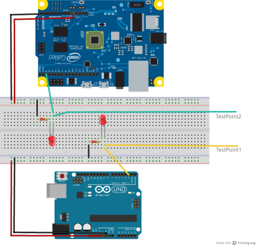
test_realtime_Galileo_vs_UNO_bbAnd the software is the same (obviously) for both boards:

void setup() 
{
    pinMode (2,OUTPUT);
}
void loop() 
{
   digitalWrite(2,HIGH);
   delay(10);
   digitalWrite(2,LOW);
   delay(10);
}

So, the behavior of code should be very very (very) simple: 10 milliseconds the led is ON and 10 milliseconds it is OFF. So the GPIO2 output is a 5V square wave, with a period of 20 milliseconds  and a duty cycle of 50%.

I connected the channel 1 of my oscilloscope to TestPoint1 and the channel 2 to TestPoint2.

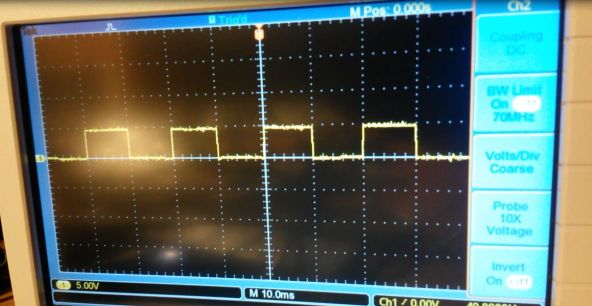
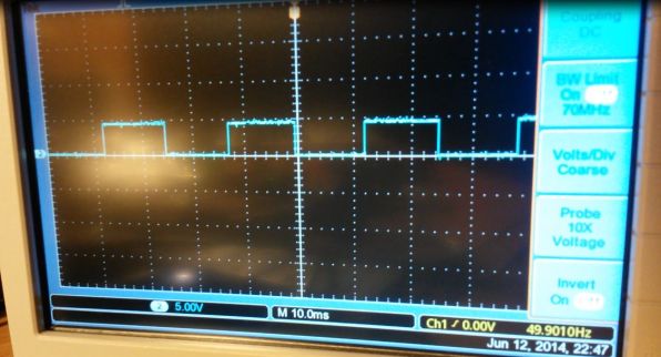
As you see the behavior of the two boards are very different: since the square wave of Arduino UNO (TestPoint 1) is fixed on the timeline with a period of 20 milliseconds, the square wave of Galileo is moving on the timeline and it has more long period than 20 milliseconds. It means that the period is not exactly 20 milliseconds, and it is variable.

This is the trace for Arduino UNO:

Oscill_arduino

As you see, the square wave is perfect (…note that the horizontal scale is 10 milliseconds for division)!

This is the trace for Intel Galileo (stopped in a certain moment, since the trace is continously shifting right):

Oscill_galileo

Well...in this case the square wave  has a period major than 20 milliseconds (because each half wave has a duration major than 10 milliseconds).

Plus, if we measure two random periods, they havent the same duration (the continuous shift of the trace is depending on this).

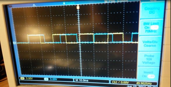
These are both waveforms:

Oscill_arduino+galileo

So, for me the result is clear: since Arduino UNO commands GPIOs using a very strict realtime, Galileo does not command GPIOs with a realtime scheduling politics.

The motivation can be probably tied to the fact that Galileo launches Arduino scripts as Linux user processes (as I noticed in my prevoius post), so without realtime characteristics.

My conclusion is that, at the moment, we can’t use Galileo as hard realtime controller for particular hardware (ie. safety critical mechanisms and so on). 😦 …

And what are your thinkings about this behaviour of Galileo? Have you found my same results?

Obviously, possible solutions and workarounds are welcome (I thinked to modify the Intel Galileo native Linux in order to add some realtime extension, i.e. RT-PREEMPT or Xenomai).

So, the discussion is open! Let me know what you think! 🙂

…Bye bye electro-babes!

Raspberry and the remote controlled relay: a low-level approach (a.k.a. “AT modem commands: the usual suspects”).

Hi my dear microelectronics F&M (female & male) friends! 😉
Here we are again with the remote controlled 220V relay using a Raspberry PI. In my previous post I used a Huawei 3G dongle with the famous gammu daemon as SMS receiver.
But… do you remember the end of the post? I was talking about a thriller/horror movie by the great Lucio Fulci.
So, the horror turned to real, since gammu-smsd, after 20-25 minutes of correct activity, decided to die himself, without any clear cause. Or better, it continued running in background but when a SMS arrived, the daemon did nothing.
I tried to “reanimate” it in several ways, removing the screensaver and the blank screen from the Raspberry, writing a script which stop/restart the daemon every 5 minutes etc. But nothing changed. 😦
I noticed also after the above mentioned 20-25 minutes, the daemon start/restart (using sudo /etc/init.d/gammu-smsd start/restart) fails.
Only a reboot works in this case….but NO PANIC please! 🙂

I think there is some problem in gammu-smsd (related to Raspbian memory management? Hmmmm…I dont want investigate it because I want to live again 😉 ).
So….I decided to try another approach, using a more simple hardware and writing myself a more simple (= with a simple maintance and debug phases) software.
I bought the ITEAD GSM Sim900 module for Raspberry PI from my usual store (Robot Italy). Price: 37 euros. I think it is a good price for a GSM/GPRS phone without keys and display! 😉
I placed my SIM in the module, then I placed the module on the Raspberry.
The module reports the unused GPIOs on the higher side, so I connected the three wires used to command the relay (Vcc, GND and command) directly to the SIM900 module.
Note that the Vcc available on the SIM900 module is 3.3V , but I noticed that my relay module works well also using 3.3V instead the requested 5V. 🙂
Note also that GPIO18 used to command the relay in my previous post, is used now by SIM900 module as software reset, so I modified my relay ON/OFF scripts in order to use GPIO22.

This is the schema of SIM900 module used GPIOs:Mappatura RasPi GPIO-ITEAD SIM900
Ok, let’s go powering the Raspberry board (with a 2A minimum power supplier, since the SIM900 can use also peaks of current of 1A).
But firstly I needed the right soundtrack for this activity, and the right soundtrack in this case is “The City Sleeps”, a powerful and aggressive crossover-progressive rock cd, in my opinion the best work of Touchstone, the band of my friend Kim Seviour.

Let’s return to us… now the Raspberry boots up but the SIM900 module is powered off (no green led is ON on the surface).
There are two ways to power it on:

  • the first approach is to simply press the power on button :-). Too simple for me.;-)
  • the second way is to set the GPIO17 high….well, you know this is my preferred solution. 😉

The python code (remember you must before install python extensions devoted to GPIO commanding, following my previous post!) is the following:

#poweron the RPI GSM SIM900 module
def PowerON_SIM900_module():
    GPIO.setup(17,GPIO.OUT)
    GPIO.output(17,GPIO.HIGH)
    return;

Raspberry talks with SIM900 module via a serial link mapped on /dev/ttyAMA0, but Raspberry locks this port at startup. The document reporting the correct actions to free the serial port (before to try to talk with the module) are in ITEAD provided C library…but they are written in chinese! 😦
So I googled aroud a lot before to find the solution to this problem, damn! 😦
This is the correct procedure in order to “unlock” /dev/ttyAMA0 port (application note taken from ITEAD blog, related to another ITEAD product):

In /etc/bootline.txt change:

dwc_otg.lpm_enable=0 console=ttyAMA0,115200 kgdboc=ttyAMA0,115200 console=tty1 root=/dev/mmcblk0p6 rootfstype=ext4 elevator=deadline rootwait

to:

dwc_otg.lpm_enable=0 console=tty1 root=/dev/mmcblk0p6 rootfstype=ext4 elevator=deadline rootwait

and in /etc/inittab comment out or delete the following line (in my case it is the last line):

# T0: 23: respawn :/ sbin / getty-L ttyAMA0 115200 vt100

Well…after this, a reboot is necessary.

The Itead GSM module...with "The City Sleeps" of Touchstone!

The Itead GSM module…with “The City Sleeps” of Touchstone!

Now, I tried using the examples provided in the official C library from ITEAD, but I encountered some error (very strange errors, such as “SIM not registered, some unpredictable error code and so on…), so I decided to talk directly to SIM900 module using AT commands.

Firstly I installed the old, well known minicom software then I connected minicom to SIM900 module with the following (the “old style values”) parameters: port: /dev/ttyAMA0, speed: 9600 bps, no flow control, no parity, 8 bit per word, 1 stop bit.

I sent some famous AT commands, such as “AT” (in order to verify if the momdem is responding), “AT+CMGS” (in order to send to my phone a text SMS), etc. and I verified that all worked well.

Quasi-incredible! 🙂

At this point I decided to implement (in Python, of course) the main code, which: receives the SMS message (many thanks to this tutorial for inspiration of this part), parses them and, if a valid command is received, it powers ON/OFF the relay. Plus, the script can send to my phone  a SMS reporting the action (Power ON/OFF) executed.

I used only three AT simple commands:

  • AT (in order to verify if the communication between module and Raspberry is OK)
  • AT+CMGS (used to send SMS messages)
  • AT+CMGL= “REC UNREAD” (used to read received unread messages)

Note that I added some delay, since I noticed that in some case the modem is a little slow to execute the AT commmands and to reply. This is the complete Python code.

But first don’t forget to install the python extension for serial communication using sudo apt-get install python-serial.

#! /usr/bin/env python

import serial
import time
import RPi.GPIO as GPIO

GPIO.setmode(GPIO.BCM)

#poweron the RPI GSM SIM900 module
def PowerON_SIM900_module():
    GPIO.setup(17,GPIO.OUT)
    GPIO.output(17,GPIO.HIGH)
    return;

def PowerONRelay():
    GPIO.setup(22,GPIO.OUT);
    GPIO.output(22,GPIO.HIGH);
    #send message to my phone that Relay is ON
    SendSMS(1);
    return;

def PowerOFFRelay():
    GPIO.setup(22,GPIO.OUT);
    GPIO.output(22,GPIO.LOW);
    #send message to my phone that Relay is OFF
    SendSMS(0);
    return;


def SendSMS(value):
   #send SMS about the action
   ser=serial.Serial('/dev/ttyAMA0',9600,timeout=1);
   ser.open();
   ser.write("at\r");
   time.sleep(3);
   line=ser.read(size=64);
   print line;
   ser.write('AT+CMGS="+39123456"\r');
   time.sleep(3);
   if (value==1):
       ser.write('Relay powered ON!\r');
   elif (value==0):
       ser.write('Relay powered OFF!\r');
   time.sleep(3);
   ser.write(chr(26));
   ser.close();
   return;

def CheckNewUnreadMessage():
   print "Check for new messages..\n";
   ser=serial.Serial('/dev/ttyAMA0',9600,timeout=1);
   ser.open();
   ser.write("at\r");
   time.sleep(3);
   line=ser.read(size=64);
   #print line;
   ser.write('AT+CMGL="REC UNREAD"\r')
   time.sleep(3);
   response=ser.read(size=200);
   print response;
   ser.close();
   return response;

#main loop
   PowerON_SIM900_module();
   print "Registering the sim...\n";
   time.sleep(15); #wait for sim to resgister to the net
   print "Started main loop\n";
   while True:
      message=CheckNewUnreadMessage();
      if(message.find("poweron")<>-1):
          PowerONRelay();
          print "PowerON commanded\n";
      elif (message.find("poweroff")<>-1):
          PowerOFFRelay();
          print "PowerOFF commanded\n";
     time.sleep(5);

As you see from the code, the new, unread SMS messages are checked every 5 seconds.

If a new message is found, it is copied in the message variable. If the message contains the poweron keyword the relay is powered ON. Else,  if it contains the poweroff keyword, the relay is powered OFF.

In both cases a SMS is sent to my phone (well… this is not my real number, also if I know you would like to know it! 😉 )

In order to auto-start the script after the Raspberry boot, you should add this command to /etc/rc.local (prior, remember to “executabilize” 😀  your script using the old chmod +x name_of_your_script.py ):

sudo /home/pi/name_of_your_script.py &

IMPORTANT NOTE: Add the “&” in order to launch in background the Python script, or you won’t be able to stop it neither using CTRL+C or swithcing shell . I will re-take the control of your Raspberry only via remote connection (using ssh)! 🙂

Now, rebooting the Raspberry, you will be able to receive/send SMS message using AT commands, power ON/OFF a 220V relay…and the most important thing: I tested the system for 3+ hours, and it worked well all time!!!

So ….I think we executed today another litlle step in my and in your “knowledge database system” called BRAIN. 🙂

Now I will take a relax time with the aid of the new Touchstone cd: “Oceans of Time”. It’s an kick-ass prog-rock album, of highest level guaranteed (as we say in Italy, it’s “Lemon guaranteed”, that is “Garantito al limone”).

Bye bye Raspberry freaks, it’s rock time for me! 😉


Arduino + Raspberry= Weather station with webcam (Part Two: the meteo data acquisition)

Hi geek boys and girls!

I hope you passed a very nice Easter holidays. Unfortunately I had the flu during these days…so no great funny time for me! 😦

…But I spent some time developing my weather station (I wrot the code for meteo data acquisition, and then I succesfully connected to the Raspberry a webcam and also a internet dongle for the remote access to the weather station).


In this post I will talk about the meteo data acquisition from Arduino and the consequent data trasmission from Arduino to Raspberry via I2C (see my previous post in order to activate the I2C link).

I decided, after some unfruitful (or simply too diffcult to implement) experiment with analog sensors, to use only digital sensors to acquire with Arduino temperature, barometric pressure and relative umidity. So I bought these sensors from Robot Italy (my preferred online store for embedded resources… as you know I love all italian products/services 😉 ):


This is the final circuit I’ve realized after some very basic integration test (click on the image for the zoom):

Centralina_meteo_v2_bbNote that I used a resistor of 4.7 KOhm instead 5 KOhm, as suggested on the DHT11 datasheet.

Ok, now it’s time to code some litttle skecth. Let’s start with Arduino.

In order to communicate with DHT11 and with MPL115A1 I used two well known libraries.

I took the DHT11 library from Arduino Playground and I took the MPL115A1 lib from the github of SMacarena (great appreciation for these very good works, and my sincere thanks to the authors 😉 ).

After some cut/paste/washing/ironing/rewashing and some other (not too many,you know me! ;-)) tests, this is the final Arduino code for the meteo data acquisition from sensors:


#include <SPI.h>
#include <MPL115A1.h>
#include <dht11.h>
#include <Wire.h> //I2C library

#define __DEBUG__ //note: I used for debug a ht1632c led display
                  //If you can't/don't use it, undef this macro! :-)
#ifdef __DEBUG__
#include <ht1632c.h>

//debug display
ht1632c dotmatrix = ht1632c(&PORTD, 7, 6, 4, 5, GEOM_32x16, 2);
#endif

//i2c settings
#define SLAVE_ADDRESS 0x04
int number_command = 0;
float value_to_send=0.0;

//I2C commands
#define TEMP 1
#define HUMI 2
#define PRES 3
#define DEW 4

//out pint for DHT11 sensor
#define DHT11PIN 2

//sensors
MPL115A1 Pressure_sensor;
dht11 DHT11_sensor;

//current atmo values
float current_pressure=0.0;
float current_humidity=0.0;
float current_temperature=0.0;
double current_dewpoint=0.0;

void setup() {
  //serial setup
  Serial.begin(115200);
  //initialize pressure sensor
  Pressure_sensor.begin();

  // initialize i2c as slave
  Wire.begin(SLAVE_ADDRESS);

  // define callbacks for i2c communication
  Wire.onReceive(receiveData);
  Wire.onRequest(sendData);
#ifdef __DEBUG__
  dotmatrix.clear();
  dotmatrix.setfont(FONT_5x8);
#endif
}

void loop() {
  //take & save pressure values
  current_pressure = GetPressure();
  GetTemp_Humidity_DewPoint();

  //print current valueson serial ...debug (remove it if you want)!
  Serial.print(current_pressure);
  Serial.print(" hPa\n");

  Serial.print (current_humidity);
  Serial.print(" % Humidity\n");

  Serial.print (current_temperature);
  Serial.print(" °C\n");

  Serial.print (current_dewpoint);
  Serial.print(" Dew point (°C)\n");
#ifdef __DEBUG__
  dotmatrix.clear();
  char tmp[20] = "";
  //pressure
  sprintf(tmp, "P=%dhPa", (int)current_pressure);
  byte len = strlen(tmp);
  for (int i = 0; i < len; i++)
    dotmatrix.putchar(5*i, 0, tmp[i], ORANGE);

  //temperaure
  sprintf(tmp, "T=%dC", (int)current_temperature);
  len = strlen(tmp);
  for (int i = 0; i < len; i++)
  dotmatrix.putchar(5*i, 8, tmp[i], RED);
  //humidity
  sprintf(tmp, "H=%d%%", (int)current_humidity);
  len = strlen(tmp);
  for (int i = 0; i < len; i++)
     dotmatrix.putchar(32+5*i, 8, tmp[i], GREEN);
  dotmatrix.sendframe();

#endif
  //delay
  delay(5000);
}

//Acquisition functions
//from sensors
float GetPressure()
{
  float hPa = Pressure_sensor.pressure();
  return hPa;
}

void GetTemp_Humidity_DewPoint()
{
  //take & save DHT11 values (temp + rel. humidity)
  int chk = DHT11_sensor.read(DHT11PIN);
  switch (chk) //check errors
  {
    case DHTLIB_OK:
      Serial.println("read OK");

      //read values
      current_humidity=(float)(DHT11_sensor.humidity);
      current_temperature=(float)(DHT11_sensor.temperature);

      //dew point
      current_dewpoint=dewPoint(DHT11_sensor.temperature, DHT11_sensor.humidity);
    break;

    case DHTLIB_ERROR_CHECKSUM:
      Serial.println("Checksum error");
    break;
    case DHTLIB_ERROR_TIMEOUT:
      Serial.println("Time out error");
    break;

   default:
     Serial.println("Unknown error");
   break;
  }
}

//dewpoint function (taken from http://playground.arduino.cc/main/DHT11Lib)
// dewPoint function NOAA
// reference (1) : http://wahiduddin.net/calc/density_algorithms.htm
// reference (2) : http://www.colorado.edu/geography/weather_station/Geog_site/about.htm
//
double dewPoint(double celsius, double humidity)
{
  // (1) Saturation Vapor Pressure = ESGG(T)
  double RATIO = 373.15 / (273.15 + celsius);
  double RHS = -7.90298 * (RATIO - 1);
  RHS += 5.02808 * log10(RATIO);
  RHS += -1.3816e-7 * (pow(10, (11.344 * (1 - 1/RATIO ))) - 1) ;
  RHS += 8.1328e-3 * (pow(10, (-3.49149 * (RATIO - 1))) - 1) ;
  RHS += log10(1013.246);
  // factor -3 is to adjust units - Vapor Pressure SVP * humidity
  double VP = pow(10, RHS - 3) * humidity;
  // (2) DEWPOINT = F(Vapor Pressure)
  double T = log(VP/0.61078); // temp var
  return (241.88 * T) / (17.558 - T);
}

//I2C callbacks

// callback for received command
void receiveData(int byteCount)
{
  while(Wire.available()) {
    number_command = Wire.read();

    if(number_command==TEMP) { //request temperature
      value_to_send = current_temperature;
    }
    if(number_command==HUMI) { //request humidity
      value_to_send = current_humidity;
    }

    if(number_command==PRES) { //request humidity
      value_to_send = current_pressure;
    }

    if(number_command==DEW) { //request dewpoint
     value_to_send = current_dewpoint;
    }
  }
}

// callback for sending data via I2C
void sendData()
{
  //convert the float values in a vector of 4 bytes to send via i2c bus
  char vector_to_send[4];
  memcpy(vector_to_send,(char*)&(value_to_send),4);
  Wire.write(vector_to_send,4);
}


Write the above skecth on the Arduino UNO and power on it….on the serial shell (and/or on the led display) you will see the vaues taken from the sensors.

Ok, let’s go ahead with the correspondant Raspberry PI code (at the moment it is implemented in an interactive way). It is a little more simple than the Arduino one (it is derived from the original one, but in thsi case I manage the transmission via I2C of float numbers, mapped each one on 4 bytes):

//ML meteo lab station v2.0 Raspi side
#include <string.h>
#include <unistd.h>
#include <errno.h>
#include <stdio.h>
#include <stdlib.h>
#include <linux/i2c-dev.h>
#include <sys/ioctl.h>
#include <fcntl.h>
#include <unistd.h>

// The PiWeather board i2c address
#define ADDRESS 0x04

//commands
#define TEMP 1
#define HUMI 2
#define PRES 3
#define DEW 4

// The I2C bus: This is for V2 pi's. For V1 Model B you need i2c-0
static const char *devName = "/dev/i2c-1";

int main(int argc, char** argv) 
{
  printf("I2C: Connecting\n");
  int file;

  if ((file = open(devName, O_RDWR))< 0) {
    fprintf(stderr, "I2C: Failed to access %d\n", devName);
    exit(1);
  }

  printf("I2C: acquiring buss to 0x%x\n", ADDRESS);

  if (ioctl(file, I2C_SLAVE, ADDRESS) < 0) {
    fprintf(stderr, "I2C: Failed to acquire bus access/talk to slave 0x%x\n", ADDRESS);
    exit(1);
  }

  int command;

  for (command= 1; command<=4; command++) {
    int val;
    unsigned char cmd[16];
    //printf("Sending %d\n", val);

    cmd[0] = command;
    if (write(file, cmd, 1) == 1) {

      // As we are not talking to direct hardware but a microcontroller we
      // need to wait a short while so that it can respond.
      //
      // 1ms seems to be enough but it depends on what workload it has
      usleep(10000);

      char buf[5];
      if (read(file, buf, 4) == 4) { //read 4 byte from i2c (a float -temp, humidity etc.-)
        float value_received;

      //convert 4 bytes received into a float
      memcpy((char*)&value_received,buf,4);
      //print the results
      if (command==TEMP)
        printf("Temperature (°C)= %f\n", value_received );
      if (command==HUMI)
        printf("Humidity (%)= %f\n", value_received );
      if (command==PRES)
        printf("Pressure (hPa)= %f\n", value_received );
      if (command==DEW)
        printf("Dew Point (°C)= %f\n", value_received );
     }
   }

   // Now wait else you could crash the arduino by sending requests too fast
   usleep(10000);
  }

  close(file);
  return (EXIT_SUCCESS);
}

Compile the Raspberry program with the same old gcc -o meteo_lab meteo_lab.c , then, if Arduino is already powered on, launch the program with ./meteo_lab

You will see on the Raspberry shell the current values for temperature, relative humidity, pressure and dew point temperature acquired (and calculated, in case of the dew point temperature) by our two sensors.

….So, you can monitor in each moment your lab weather condition! 🙂

Ok, I think you are thinking it is not too much….So, in the next posts we will see how to visualize these data (with a good webcam image on the side) on a web page accessed from internet… this is much more interesting or not? 😉

Bye bye geeks, c ya soon!


Arduino + Raspberry= Weather station with webcam (Part One: the I2C link)

Hi geek boys and girls!

After few more technical and obscure posts, finally I give some (original? I don’t think so…but it’s funny!) creative idea for your *ware open source projects.

With this post I would like to start building a open source meteo weather station.

In order to do this task I think you could connect together, such as a great cup of Mojito 🙂 :

  • A set of sensors (i.e. humidity, barometric pressure, temperature)
  • One little camera (i.e. we could start with an inexpensive webcam…if the weather conditions would permit its use!)
  • One Arduino UNO (or one Intel Galileo ;-))
  • One Raspberry PI Model B
  • One GSM module, or more simply, one less expensive USB internet key (to access via internet to your station)

Ok, first question: why Raspberry AND Arduino (and not only one board)?

Well… I would like to use Arduino to manage all sensors (especially if they would be analog sensors, since Raspberry doesn’t have analog inputs), and I would like to use Raspberry to manage the webcam and the communication with the external world via the GSM module (since it has  high-level functiona).

So I will use Arduino as acquisition board and Raspberry as data collector and as webserver.

Raspberry and Arduino can talk to each other using some different approaches, but I would like to use the I2C protocol, because it’s very simple and very well supported by Raspbian distribution and by native Arduino libraries.

I found this interesting post by Peter Mount in order to safely connect Arduino (as slave) and Raspberry (as master) using I2C.

In order to activate the I2C bus on Raspberry Peter reports five step on Raspbian:

  1. Open /etc/modprobe.d/raspi-blacklist.conf and comment the line reporting  i2c-bcm2708 (so, I2C is removed from blacklist)
  2. Add i2c-dev to the /etc/modules in order to activate the I2C driver at boot
  3. Install i2c-tools using thje well known apt-get install command
  4. Add the “pi” user to the i2c group (using the adduser pi i2c command) in order to let the user “pi” can access to I2C
  5. Reboot the Raspberry board.

In order to phisically connect Arduino and Raspberry via I2C:

  1. Connect SDA Raspberry pin (GPIO0) to SDA Arduino UNO pin (Digital IO 4)
  2. Connect SCL Raspberry pin (GPIO1) to SCL Arduino UNO pin (Digital IO 5)
  3. Connect the ground pins fo the two boards

Remember that Raspberry uses 3.3V as base voltage and Arduino UNO uses 5V…so pay attention: OR if you use a voltage converter in the I2C connection OR you are sure that you are using Arduino as slave I2C device and Raspberry as master I2C device. The first one choice is the best…but I love the risks (the risk in this cas is to have a “Raspberry flambé” 😉 ).

Ok, let’s go ahead. I used a little analog temperature sensor (the one provided in all starter kits by Analog Devices! 😉 ) connected to Arduino UNO (in the Analog input A0)  and then I modified the code provided on the Peter Mount blog in order to read the ambient temperature using Arduino and send it to Raspberry via I2C bus.

This is the simple circuit I used (zoom to better view the links):

20140411_084154

The code on Raspberry is the following (it’s directly taken from Peter Mount Blog, except for only one correction: I defined file as FILE* since declared as int raised a segmentation fault on fclose call….):

#include <string.h>
#include <unistd.h>
#include <errno.h>
#include <stdio.h>
#include <stdlib.h>
#include <linux/i2c-dev.h>
#include <sys/ioctl.h>
#include <fcntl.h>
#include <unistd.h>

// The Arduino board i2c address
#define ADDRESS 0x04

//For V1 Model B you need i2c-0
//For V2 you need i2c-1(...in my case I have a V2 Raspberry Pi! :-) )
static const char *devName = "/dev/i2c-1"; //)

int main(int argc, char** argv) {
 if (argc == 1) {
   printf("Supply one or more commands to send to the Arduino\n");
   exit(1);
   }

 printf("I2C: Connecting\n");
 FILE* file;
 if ((file = open(devName, O_RDWR)) < 0) {
   fprintf(stderr, "I2C: Failed to access %d\n", devName);
   exit(1);
   }

 printf("I2C: acquiring buss to 0x%x\n", ADDRESS);
 if (ioctl(file, I2C_SLAVE, ADDRESS) < 0) {
   fprintf(stderr, "I2C: Failed to acquire bus access/talk to slave 0x%x\n", ADDRESS);
   exit(1);
   }

 int arg;
 for (arg = 1; arg < argc; arg++) {
   int val;
   unsigned char cmd[16];
   if (0 == sscanf(argv[arg], "%d", &val)) {
     fprintf(stderr, "Invalid parameter %d \"%s\"\n", arg, argv[arg]);
     exit(1);
     }

   printf("Sending %d\n", val);
   cmd[0] = val;
   if (write(file, cmd, 1) == 1) {
    // As we are not talking to direct hardware but a microcontroller we
    // need to wait a short while so that it can respond.
    // 1ms seems to be enough but it depends on what workload it has
    usleep(10000);
    char buf[1];
    if (read(file, buf, 1) == 1) {
      int temp = (int) buf[0];
      printf("Received %d\n", temp);
      }
   }

   // Now wait else you could crash the arduino by sending requests too fast
   usleep(10000);
  }
  fclose(file);
  return (EXIT_SUCCESS);
}


The code on Arduino UNO  is very simple and it is derived from the code taken from Peter Mount Blog:

#include <Wire.h>

#define SLAVE_ADDRESS 0x04

int number = 0; //command identifier (sent by Raspberry)
double temp; //variable used to store the temperature
const int sensorPin = A0; //pin where we read the temperature from the sensor
 
void setup() {
 // initialize i2c as slave
 Wire.begin(SLAVE_ADDRESS);
 // define callbacks for i2c 
 Wire.onReceive(receiveData);
 Wire.onRequest(sendData);
}
 
void loop() {
 delay(100);
 temp = GetTemp();
}
 
// callback for received data from I2C
void receiveData(int byteCount){
 while(Wire.available()) {
 number = Wire.read();
 
 //"2" is the command sent by Raspberry Pi in order to have the 
 // temperature as answer on I2C from Arduino
 if(number==2) { 
     number = (int)temp; //Arduino in this case sends the integer value of temperature
  }
 }
}
 
// callback for sending data on I2C
void sendData(){
 Wire.write(number);
}

float GetTemp(){
 // read the value on AnalogIn pin 0 
 // and store it in a variable
 int sensorVal = analogRead(sensorPin);

 // convert the ADC reading to voltage
 double voltage = (sensorVal/1024.0) * 5.0;
 
 // convert the voltage to temperature in degrees C
 // the sensor changes 10 mV per degree
 // the datasheet says there's a 500 mV offset
 // ((voltage - 500mV) times 100)
 double temperature = (voltage - .5) * 100;
 return temperature;
}

Ok… we can now download the cvode on Arduino and we can compile the client software on Raspberry Pi using the good old command:

gcc -o TakeTemp main.c

So, once powered on Arduino and verified using the Raspberry command

i2cdetect -y 1

that Arduino is correctly detected with I2C address 0x04, write in the Raspberry command line

./TakeTemp 2

Note that “2” is the I2C command used to receive from Arduino the acquired temperature (see the Arduino code above).

…If all will work correctly, you will read as output the integer value of the sensor temperature, acquired by Arduino and sent to Raspberry via I2C!

Yeah geek guys (and obviously geek gals)…”this is one small step for the human race”, but it’s also a good start to develop an open source meteo station. 😉

And now… a good relax!:-) That’s all folks (for this time)! 😉

…Bye bye!