Hi my dear female & male microelectronics geeks!
This time I will build an interesting object: a remote controlled relay using a Raspberry PI as SMS messages receiver and parser (and -obviously- as relay phisical controller).
I will use this stand-alone (sub)system with my meteo station system. If you want to read more about the meteo station, in the previous posts I described the I2C communication between the acquisition board (Arduino UNO) and the station controller, the model (hardware and software) of the acquisition board.
In this post we will PLAY WITH THE HIGH VOLTAGE, so… pay attention,please. 🙂
Rememeber that when we use the high voltage..the only safe thing you can consider is the GROUND, so… again, pay attention please! 🙂
Why high voltage? Well… it’s simple.
Because I would like to power on/off my meteo station via remote commands (since at the end of this “technical adventure” I will install my meteo station in a very beautiful place, but a little far from my home).
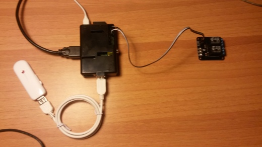
In order to do that, I would like to use a simple (sub)system, consisting of one Raspberry PI (for this purpose you can use also the less expensive model A, but in my project I will use again a Model B.Yeah, you know I love this board …but I assure you I’m preparing some surprise also with my new Olinuxino A20! 😉 ), one Itead 2-way Relay Module (bought as usual from Robot Italy), one multiple power connector bought (…from my father) at the cheapest general-purpose shop in my little city (it is called “Risparmio Casa”, in English it should be something like “Savings -for the- House”), and, last but not least, one USB 3G dongle (I used an old Huawey K3715 compatible E169, marketed by Vodafone, with a TIM sim inside) which I will use as “mobile phone” in order to receive SMS messages.
In this case I will not use it as “internet 3G dongle” because:
- I want to command the power on/off even if the 3G signal is not present
- Sending single SMS messages is cheaper than a flat 3G connection (in Italy, I don’t know if the situation is the same in other countries)
- The power consuption is lower if the dongle is not connected to 3G
Ok, let’s go with the experiment! 😉
Commanding the relay using Python
I took the inspiration for this step , from this post of the italian blog “Raspibo.org”
Let’s install something!
#sudo apt-get update
#sudo apt-get install python-rpi.gpio
#sudo apt-get install python3-rpi.gpio
Well, after this you can connect Raspberry and the Itead relay module .
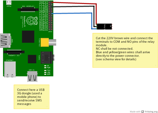
GPIO18 will be used as command signal for relay, plus you will connect the Raspberry 5V/GND pins to the module Vcc/Gnd pins. This is the Fritzing schema:
Then you can modify the multiple power connector in the following mode: remove a part of external protection from the cable (pay attention in this operation, please!), then cut the 220V brown wire and connect the terminals to COM and NO pins of the relay module. NC shall be not connected. Blue and yellow/green wires shall arrive directly to the power connector.
Ok, now we can test the relay (with the 220V power NOT connected, for the moment).
Firstly we must write a script in order to initialize to LOW the GPIO18 pin at Raspberry startup. The script will be:
#!/usr/bin/env python
import Rpi.GPIO as GPIO
GPIO.setmode(GPIO.BCM)
GPIO.setup(18, GPIO.OUT, initial=GPIO.LOW)
Then, you can save it where you want, and you must to change the mode in order to declare the script as executable:
#chmod +x initialize_GPIO18_script.py
…But the very important thing is to add the following line to /etc/rc.local:
sudo /path_to_initialize_GPIO18_script/initialize_GPIO18_script.py
and execute a reboot of the board.
After the reboot, the GPIO18 will be correctly initialized, so you could test the relay functionality. In order to close the relay you will write the following script:
#!/usr/bin/env python
import Rpi.GPIO as GPIO
GPIO.setmode(GPIO.BCM)
GPIO.setup(18, GPIO.OUT)
GPIO.output(18, GPIO.HIGH)
and in order to open the relay you will write the following script:
#!/usr/bin/env python
import Rpi.GPIO as GPIO
GPIO.setmode(GPIO.BCM)
GPIO.setup(18, GPIO.OUT)
GPIO.output(18, GPIO.LOW)
Note that all the executions of GPIO-related scripts will be possible only using “sudo” before the commands.
Well… if your scripts work well, open the relay (=led powered off on the Itead module): this is the safer state.
Now it’s the moment to connect the multiple power connector to the 220Volts plug on the wall….but, REMEMBER THAT THIS OPERATION CAN BE DANGEROUS AND YOU MUST USE ALL AVAILABLE PROTECTIONS in order to reduce risks. Remember that you are now playing with HIGH VOLTAGE, so PAY ATTENTION.
To test the relay behavior now you connect a lamp (or something else) to the multiple power connector and use the above scripts to power on/off it.
…..Aufffff, I hope all worked well, and you haven’t burnt your home! 😉
Connecting the USB 3G dongle and configuring it in order to receive (and send) SMS messages
Ok, now a little more relaxed activity: we must receive SMS messages using a 3G dongle and we must to parse them in order to command the relay.
I’ve done the following steps in order to make all things work without problems (after maaaaaaaany experiments, overall tied to the files/directories permissions and to users execution policies…. 😦 ).
1. Power Off your Raspberry
2. Connect the USB 3G dongle, then power on the Raspberry. My dongle is correctly recognized by Raspbian as 3G modem on /dev/ttyUSB0 [IMPORTANT NOTE: some USB dongle -i.e. Huawey E1820- is recognized by Raspian as CD-ROM… so you should use some “howto” regarding the utility usbmodeswitch in order to correctly recognize the modem inside the dongle]
3. Install gammu and gammu-smsd. Gammu is used to send SMS message, gammu-smsd is the daemon used to receive the SMS.
#sudo apt-get install gammu
#sudo apt-get install gammu-smsd
4. Configure the file /etc/gammu-smsdrc in the following way:
port = /dev/ttyUSB0
connection= at19200
[...]
logfile = /home/pi/log-gammu.txt
service = file
RunOnReceive = sudo /home/pi/Script_relay/sms_relay.py
[...]
inboxpath= /home/pi/Script_relay/inbox_sms/
5. Save the file, then add the user “gammu” to “sudoers” group of your Raspberry, using the tool visudo:
#sudo visudo
It will open /etc/sudoers.rc…so you append the following line to the file :
gammu ALL=(ALL) NOPASSWD: ALL
[NOTE: you can report /home/pi/Script_relay/sms_relay.py instead of ALL, for security reasons]
6. Save the file and Reboot you Raspberry. The gammu-smsd daemon starts automatically at the end of boot process.
7. Verify that in /home/pi/gammu-log.txt there arent’t strange errors (tied to communication between Raspi and the dongle). I encountered these errors when I installed gammu-smsd without the dongle already connected. Anyway, in this case you can remove the installation and you can reinstall gammu-smsd:
#sudo apt-get –purge autoremove gammu-smsd
#sudo apt-get gammu-smsd
8. Create the filesystem used by the gammu-smsd configuration:
#mkdir /home/pi/Script_relay
#mkdir /home/pi/Script_relay/inbox_sms
#chmod 777 /home/pi/Script_relay/inbox_sms
[NOTE: I imposed the simple mode 777 in order to permit to “gammu” user to save the SMS messages in this folder -and it’s work-, but you can use some more secure access]
9. Create the code for /home/pi/Script_relay/sms_relay.py in the follwing way:
#!/usr/bin/env python
import Rpi.GPIO as GPIO
import sys
GPIO.setmode(GPIO.BCM)
#note we don't initialize the initial value of GPIO18, we use the current status
GPIO.setup(18, GPIO.OUT)
#the filename of the SMS is passed as argument to the script from the RunOnReceive gammu-smsd option
filename=str(sys.argv[1])
complete_filename="/home/pi/Script_relay/inbox_sms/"+filename
sms_file=open(complete_filename,"r")
message=sms_file.read(160) #note that a not-parted SMS can be maximum 160 characters
if (message.find("poweron")<>-1):
     GPIO.output(18, GPIO.HIGH)
elif (message.find("poweroff")<>-1):
     GPIO.output(18, GPIO.LOW)
That’s all folks!
If all worked correctly, sending now to the dongle telephone number a SMS containing the keyword poweron you will see that the relay will be powered on, and sending an SMS containg the keyword poweroff you will see that the relay will be powered off.
…It’s a magical thing, don’t you think that? 😉
Possible improvements to the project (I give you them as exercises 🙂 )
1. Send a SMS message to a number (it should be the number of the phone which commanded the power on/off)when the relay has been powered on/off. You should modify the sms_relay.py adding a call to the gammu command line tool (find one of the many examples on internet for the usage). Note that the tool must be configured (his configuration file is /home/pi/.gammurc) with the following data:
port = /dev/ttyUSB0
connection= at19200
…But for this functionality there is a little (=big 😦 ) problem: gammu-smsd blocked the /dev/ttyUSB0, so….what could be a possible solution?
2. Add to the /etc/gammu-smsdrc file one filter in order to accept SMS message only from YOUR phone. This is not difficult, there is a configuration parameter to add in the file (with the “white-listed” numbers)… you can find it in the gammu-smsd user guide! 🙂
Ok boys and girls, today we used the high voltage… you know that for a software and/or microelectronics engineer this is like a bungee-jumping. 😀
So, now I need only a good grappa an an italian horror (or thriller) movie of the ’70-’80 on my television.
Do you like Lucio Fulci movies?
I know he is very famous all around the world (…except than in Italy 😦 ).
My Fulci preferred movie is “The New York Ripper” (italian title: “Lo Squartatore di New York”)…. I need a very relaxing night, after this dangerous and stressing post! 😉
Bye bye, see you soon!


