Hi hi-tech friends (…with a prominent geek attitude 🙂 )!
This time I would like to talk about…MUSIC! Ta-daaaa!!
As you know I am also a musician, and I produce freely downloadable music from my music website www.marcolastri.net (only italian language, sorry! ).
I have a large set of keyboards and synthesizers in my studio, and I have also a Roland AX-7, a “wearable” MIDI controller keyboard similar to a guitar (today these instruments are called “keytars” 😉 ). This keytar is used also by the mighty Herbie Hancock…. 😉
This keytar has also a great feature: it can be power by 6 AA batteries….but you will have always the midi cable in order to command your sound generator or expander (or software synth etc.). The midi cable is a limitation to your performance freedom on stage…so I want to cut it! 😉
There are some good wireless solution off-the-shelf, for example the Mid-Air product from M-Audio….and the price is not so low. 😦
…So I want to realize a DIY solution, using two Arduinos UNO, two XBee Shields and two XBee modules: this is the Garretlabs MIDin project! Ta-daaaa!
I bought from my preferred store (www.robot-italy.com) the following components:
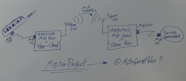
Then I connected these components to two Arduino UNO boards in order to realize: one component working as MIDI Receiver-XBee Sender and one component working as MIDI Sender-XBee Receiver.
Thi is the system overview…design handmade by ML! 😉
First step: program the XBee modules
This is the more complex step…I don’t love it but (unfortunately) it is necessary.
We must to setup the Series 2 modules in order to enable the “AT mode” communication (the Series 2 chips support also another -more complicated- configuration, in order to realize very complex networks of XBee modules). In other words, we must to program the devices in order to simulate a point-to-point-connection, a true serial wireless connection.
The best tutorial I’ve found on the internet is the following: http://tutorial.cytron.com.my/2012/03/08/xbee-series-2-point-to-point-communication/comment-page-1/. I used it step-by-step in order to configure my XBee modules…and it worked great! 😉
Firstly I downloaded and installed the X-CTU utility (only for Windows… 😦 ) from Digi site.
After this, I attached a wire to the RESET pin of the Arduino and I connected it to GND. Then I connected the XBee Shield with the XBee module onboard (remember to set his jumper on “USB”): this is the way to directly access the XBee modules for programming them using Arduino board USB connection. In other words, to program the XBee modules it’necessary to disable the ATMEGA chip, so…or you remove it, or you connect to GND the RST Arduino pin. 😉
So, I used as network ID the suggested number (1234), then I configured one module as Coordinator AT (setting in the values SH/SL of serial number of Router module), and I configured the other module as Router AT (setting in the values SH/SL of Serial Number of Coordinator module).
Well, once configured, the two modules start to “talk” each other, and the leds on shields start to blink. To test the correct configuration you can use the procedure well explained in the http://tutorial.cytron.com.my/2012/03/08/xbee-series-2-point-to-point-communication/comment-page-1/.
IMPORTANT NOTE: I used the default speed of serial connection (9600 bps) for XBee modules, since I noticed that if I change the data speed, the USB connection from Arduino IDE to Arduino in order to download applications should fatally fail.
Second step: the MIDI receiver-XBee sender
The difficult step is passed…so, one moment of relax now! 😉
Ok, let’s start with the secdond step.
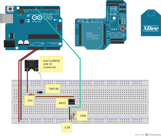
This MIDI receiver/XBee Sender has one MIDI connector in order to receive MIDI signals from a synthesizer, the software collect them, then it uses the XBee serial link to send MIDI signals to the other system component (see the third step).
The circuit is very simple…. and it is based on the standard MIDI-IN circuit. See http://www.midi.org/techspecs/electrispec.php to see the details. I modified it a little (especially the optocoupler)…in order to match the parts I had in the “Garret” at the moment 😉 !
The components are:
- 1x Optocoupler 4N35
- 1x Diode 4148
- 1x 100KOhm resistor
- 1x 220Ohm resistor
- 1x 3.3KOhm resistor
Note that in the schema I added the XBee module and the XBee shield on the right side of Arduino, in order to better explain the connections, but OBVIOUSLY their must be mounted ON the Arduino! 🙂
The software is simply a MIDI messages collector and re-sender.
Note that I used a buffer to memorize a certain number of MIDI message before to send them, because if wen I receive a message I resend it immediately, I could loose another MIDI message incoming in the meantime. So, I used a “buffering approach”. I verified -as musician 🙂 – that the latency due to buffering is very (very) low, so this approach is acceptable. 😉
Note also that I use the Software Serial (the RX is on pin 10) to receive MIDI messages, because XBee must use the Serial port.
 #include <SoftwareSerial.h>

SoftwareSerial MidiSerial(10, 11); // RX, TX

byte in_buffer[1024]; //maximum number of bytes arrived in one cpu cycle
unsigned int received_bytes;

void setup()
{
  Serial.begin(9600); //XBEE transmission
  MidiSerial.begin (31250); //MIDI transmission

  //led 13 used for debug
  pinMode(13, OUTPUT);
  digitalWrite(13, LOW);

  received_bytes=0;

}

void loop()
{
  if(MidiSerial.available()>0)
  {
      received_bytes=MidiSerial.available();
      for (int i=0;i<received_bytes;i++)
        in_buffer[i]=MidiSerial.read();  //save in the buffer all bytes arrived from MIDI port

      //write all bytes arrived in the present cycle (so, the input is decoupled from the output)
      digitalWrite(13, HIGH);
      for (int i=0;i<received_bytes;i++)
      {
        Serial.write(in_buffer[i]);
      }
      digitalWrite(13, LOW);

      //reset the counter of received bytes in the cycle
      received_bytes=0;
  }
}
In order to write the program on Arduino, you must set the XBee jumper on “USB” position (and obviously you must to remove the cable to ground connected to the RST pin…see step one!). After programming, you should set the jumper on “XBee” position.
Third step: the MIDI sender-XBee receiver
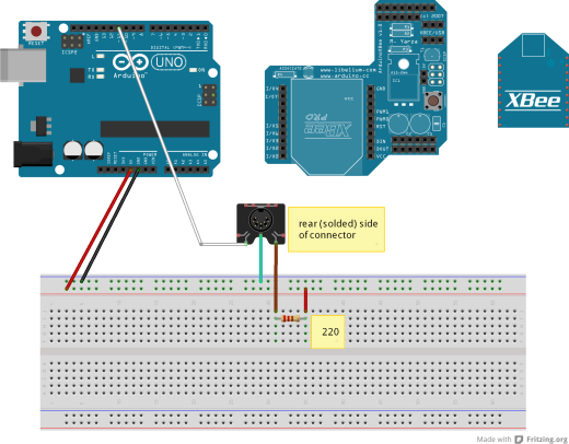
Well, this component is more simple than the previous: it receives the MIDI messages from Xbee serial wireless link and it resend them to the MIDI Out port, in order to command a sound generator, a expander or another synth.
Only one component in this case:
- 1x 220Ohm resistor
This is the (simple) circuit. As you can note, the MIDI In and Out circuits are NOT mirrored (this is the standard)! ….What a strange design choice!!! 🙂
And this is the Arduino software (the MIDI management functions are taken from http://arduino.cc/en/Tutorial/Midi?from=Tutorial.MIDI):
#include <SoftwareSerial.h>

SoftwareSerial MidiSerial(10, 11); // RX, TX

void setup()
{
  Serial.begin(9600); //XBEE transmission
  MidiSerial.begin (31250); //MIDI transmission

  //led 13 used for debug
  pinMode(13, OUTPUT);
  digitalWrite(13, LOW);

}

void loop()
{

  if(Serial.available() > 0)
  {
    digitalWrite(13, HIGH);
    MidiSerial.write(Serial.read()); //receives the midi messages via XBEE...and send it to Synth
    digitalWrite(13, LOW);
  }
  //Test function
  //SendAllNotes();
}
////////////////////////////////////////////////////////////////////////////////////////////
//
// MIDI HELPER FUNCTIONS (taken from http://arduino.cc/en/Tutorial/Midi?from=Tutorial.MIDI)
//
////////////////////////////////////////////////////////////////////////////////////////////

void SendAllNotes() {
  // play notes from F#-0 (0x1E) to F#-5 (0x5A):
  for (int note = 0x1E; note < 0x5A; note ++) {
    //Note on channel 1 (0x90), some note value (note), middle velocity (0x45):
    digitalWrite(13, HIGH);
    MIDICommand(0x90, note, 0x45);
    delay(100);
    digitalWrite(13, LOW);
    //Note on channel 1 (0x90), some note value (note), silent velocity (0x00):
    MIDICommand(0x90, note, 0x00);
    delay(100);

  }
}

//  Send a midi command.  Doesn't check to see that
//  cmd is greater than 127, or that data values are  less than 127:
void MIDICommand(int cmd, int pitch, int velocity) {
  MidiSerial.write(cmd);
  MidiSerial.write(pitch);
  MidiSerial.write(velocity);
}
Now you can write the software on Arduino,
And…well… that’s done! 🙂
To test the system you can connect a master keyboard (better if it is a keytar! 😉 ) to Midi Receiver-XBee Sender and a sound generator to Xbee Receiver-Midi Sender…. and you can try to emulate Sandy Marton’s (one of my 80’s Italo Disco heroes) performances with their faboulous keytars!
This is the mighty Sandy in one of his mighty performances:
Bye bye people, now I go to play some note with my AX7…I need a music overdose (I think today I will write an italo-disco song)! 😉
And…remember tio visit my music site www.marcolastri.net!


