The dark side of porting Arduino sketches on Intel Galileo (part two)

Hi geek friends ( female & male)!

This is the post of the “real dark side” of porting external hardware control from Arduino to Intel Galileo. And, it’s just an example, a little sketch of the real work.

…Are you ready? Before starting this dangerous “trip” I want you send a first warning: unfortunately the x86 (the architecture of Intel Quark, the CPU inside the Intel Galileo) is very different from the architecture of the AVR (the Arduino MCU). So, registers, memory spaces etc. are completely different (Monty Python docet!).

My (insane, very insane 🙂 ) idea was to port some “lower level” code from Arduino Mega to Intel Galileo, in order to verify on my skin the real hardware differences between the two platforms and also in order to compare the “hardware level” performances.

I opened the “Arduino on Android kit” (a very appreciated gift from Monica! ;-)) and I found two very interesting hardware components: two ht1632c bicolor (red/green) led displays.

What a cool find! 😉 I love the shifting dysplays in the chinese stuff stores! 😀

So… I googled for already working driver on Arduino for these devices. I found some very interesting solution. The first one library is here, and it is very powerful and fast in my little opinion.

I tried on the Arduino Mega all the library demo sketches and I verified the correct work for my two displays. Looking inside the code I saw that all the library is based on AVR registers programming (using in every instruction all the possible bit-field functions, bit masks, bitwise operators and so on…).

Weahhhh…ok, I know this is the correct mode to write a driver, and it’s true that I wanted to go to a “lower level”…. but not so low! 😀

Indeed, once ported the code inside the Intel Galileo IDE, a so high number of “undefined references”  gave me the real proof that NOT ALL the AVR architecture has been ported by the Intel team in the Galileo development environment…. so we have two natural choices: the first one is to rewrite all the library using the Quark registers instead the AVR registers (but we are inside a Linux environment, it’s no so simple to manipulate the low level hardware without interact with the Linux kernel) or, the second choice is try to write a library at an higher level, using only the basic functionalities  (so using the native APIs) of Arduino.

I preferred the second oprion (…you suspected it, I know! :-)), so  I started looking for a little simpler (and without too many functionalities) library working directly on Arduino GPIOs, in order to simplify the porting phases (and possibly without losing my love in microelectronics 😉 )

I found the code  and the circuit reported on Arduino Playground (I love this site…because it’s a made in Italy product. You know, we don’t have only corruption, not-so-effordable persons & politicants… and soccer 😉 )….and -oh, oh- it was exactly what I was looking for. 😀

I took all the code and, after I removed the parts (code and hardware) related to the real time clock (because actually I don’t have a RTC!), I compiled the code in the Arduino IDE and I flashed it on my Arduino Mega. I obtained a “fixed hours and day” red and green clock on my two led displays. The draw of the displays is very fast (approx. immediate).

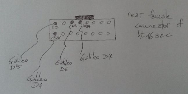
Ok, I ported the same code in the Galileo IDE and I obtained some compilation errors, tied to the hardware differences between Arduino and Galileo. This is the pinout for display I used:

ht1632_pinout

Mainly Galileo IDE doesn’t have the <avr/pgmspace.h>… it’s natural since it’s a x86 CPU…but it is also a problem, because the great majority of third party lins use this file and its definitions (especially to declare some variable directly in the program flash, since Arduino doesn’t have so much RAM).

But since Galileo has a lot of RAM, it isn’t necessary to save data in the flash program space.

So, following the defines reported in avr/pgmspace.h , I changed in the file font1.h definitions:

PGM_P CHL[] PROGMEM= [...]

in a simple

char* CHL[] = [...] .

After this, I removed the #include <avr/pgmspace.h> in the main .ino file,  and in the same file (function set_buffer()) I changed the line :

memcpy_P(buffer[j], (PGM_P)pgm_read_word(&(CHL[j+pos])), 8);

in

memcpy(buffer[j], (const char *)(&(CHL[j+pos])), 8);

Once resolved the errors, I compiled and flashed the code on Galileo.

I obtained a strange behavior: instead of the clock some strange character appeared on the two displays, with a very very (very! 😦 ) slow draw rate.

Ok, I think the strange characters are tied on a non perfect alignment on the memory in the x86 respect to the AVR  or to different sizes of some data type, especially due to the above memcpy porting  (but I didn’t investigated so much because I was worried by the displays slow draw rate). So, I changed the initial code in order to write a text on display pixel by pixel (note that this is the same approach of the original code), starting from drawing a single pixel in a certain (x,y) coordinate.

The differences between the initial code and my modified code can be easily found comparing the code in the page of Arduino Playground and the attached the zip file.

I attach the complete code as zip file since the code is too long for a blog post…and I think this post is already too long. But remember this is a “difficult” post. It MUST be long! 😉 Please excuse any commented code and some commentsin Italian…I know this is a lab “spaghetti code” . 😉

Ok, using this code the text is shown in the correct way on Intel Galileo (….to be investigated the strange drawing with the original code! 😉 ), but using Galileo the draw process took approx. 20 seconds (versus the Arduino result, which is minor than 1 second!!!) and with some different delay times between one pixel draw and the subsequent.

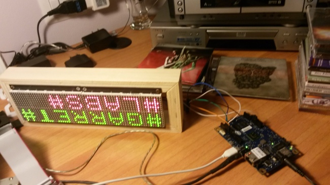
This is the final result (sorry for the up-down text, but I have very short wires between Galileo and the display…;-) ). In the background of the photo you can see two beautiful italian progressive rock cds by Maurizio di Tollo and by La Maschera di Cera (both my good friends), which have been the inspiration for my porting work. 🙂

20140330_104925

Any ideas for this behavior (the slow drawing process)? I have one…but I don’t know if it is the correct idea.

As you know, Intel Galileo runs the Arduino sketches as Linux user processes (so, all kernel calls, interrupts, threads etc. have a higher priority  than a user process and so they can interrupt the execution of the Arduino skecth), whereas in Arduino no operating system is used (the sketch is a well-known “bare metal” code), so a real time behavior is a “true real time” behavior, and the sketch runs at the highest speed without interruptions.

So… what can I say? Intel Galileo is a really fast machine (compared to Arduino Mega or UNO) but in my little opinion it has some little “real time” problem when using the Arduino IOs (also I know my code is not optimized at all!!! 😉 ). And you? What do you think? 😉

Please, express your geek thinkings, and find al my errors! I will appreciate each contribution, especially  tied to my errors….the knowledge is always a mindstorm! 😉

Bye bye folks, now I go on my sofa to drink my brandy.

Another day is passed…another post is written. 🙂

ML
 

The dark side of porting Arduino sketches on Intel Galileo (part one)

….Hi folks, here we are again!

As promised in my last post, this time we start to talk about the porting procedures (and issues) from Arduino UNO/Mega ADK to Intel Galileo.

One can think the porting is painless (since Intel Galileo is born from a “collaboration” between Intel and Arduino guys), but unfortunately the truth is different. My experience tell me that’s the naked reality behind the embedded world…but this is a sad

Ok, the first thing you will notice porting a sketch from Arduino IDE to Galileo IDE is that NOT ALL Arduino libraries have been ported correctly in the Galileo environment (do you remember my old post? The String class is one of these examples…), so you could encounter a great number of “undeclared” variable or function errors. Someone told me that also TFT library doesn’t work correctly in Galileo….I’m a little sad…. 😦

But today we talk about some “working” library, in order to gain some succesful result before the “real  battles”! 😉

For example, the I2C library seems to work in the same way in Arduino environment and in the Galileo environment. The I2C is a serial communication protocol used to connect Arduino (and in general all processors) with external devices.

An exampre of therse devices are EEPROMs of 24cXX series. I used these EEPROMs for maaaaaaany years, because simply they use the I2C protocol, so they are serial (=slower, I know it)….but they use few wires to be commanded. And it isn’t a little thing when using Arduino UNO! 🙂

…The parallel EEPROMs such as 28cXX are much faster but they use too much electrical links (and Arduino UNO doesn’t have so many GPIOs!).

Right, let’s go ahead. In order to read/write from/to the 24cXX EEPROM I used a very nice library found on Arduino Playground .

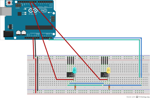
Then I designed a little circuit (with Fritzing) in order to use one 24c64 (64kbytes) EEPROM and one 24c256 (256 kbytes). This is the circuit (please…use Intel Galileo instead Arduino UNO, with a pin-to-pin correspondance, and all should be work correctly! 😉 ):

EEPROM_doppia_v2_bb

Then I wrote a very simple “dummy” sketch in order to execute some basic operation on the EEPROMs.

#include <Wire.h> //Arduino I2C library...which works also on Intel Galileo!

//////LIBRARY functions taken from http://playground.arduino.cc/Code/I2CEEPROM

  void i2c_eeprom_write_byte( int deviceaddress, unsigned int eeaddress, byte data ) {
    int rdata = data;
    Wire.beginTransmission(deviceaddress);
    Wire.write((int)(eeaddress >> 8)); // MSB
    Wire.write((int)(eeaddress & 0xFF)); // LSB
    Wire.write(rdata);
    Wire.endTransmission();
  }

  // WARNING: address is a page address, 6-bit end will wrap around
  // also, data can be maximum of about 30 bytes, because the Wire library has a buffer of 32 bytes
  void i2c_eeprom_write_page( int deviceaddress, unsigned int eeaddresspage, byte* data, byte length ) {
    Wire.beginTransmission(deviceaddress);
    Wire.write((int)(eeaddresspage >> 8)); // MSB
    Wire.write((int)(eeaddresspage & 0xFF)); // LSB
    byte c;
    for ( c = 0; c < length; c++)
      Wire.write(data[c]);
    Wire.endTransmission();
  }

  byte i2c_eeprom_read_byte( int deviceaddress, unsigned int eeaddress ) {
    byte rdata = 0xFF;
    Wire.beginTransmission(deviceaddress);
    Wire.write((int)(eeaddress >> 8)); // MSB
    Wire.write((int)(eeaddress & 0xFF)); // LSB
    Wire.endTransmission();
    Wire.requestFrom(deviceaddress,1);
    if (Wire.available()) rdata = Wire.read();
    return rdata;
  }

  // maybe let's not read more than 30 or 32 bytes at a time!
  void i2c_eeprom_read_buffer( int deviceaddress, unsigned int eeaddress, byte *buffer, int length ) {
    Wire.beginTransmission(deviceaddress);
    Wire.write((int)(eeaddress >> 8)); // MSB
    Wire.write((int)(eeaddress & 0xFF)); // LSB
    Wire.endTransmission();
    Wire.requestFrom(deviceaddress,length);
    int c = 0;
    for ( c = 0; c < length; c++ )
      if (Wire.available()) buffer[c] = Wire.read();
  }

///////////end of I2C EEPROM library

  void setup() 
  {
    //pinMode(9, INPUT); 
    pinMode(10, OUTPUT); //used to power on/off 24C256 EEPROM
    pinMode(11, OUTPUT); //used to power on/off 24C64 EEPROM

    //power off EEPROMs
    digitalWrite(10, LOW);
    digitalWrite(11, LOW);

    Wire.begin(); // initialise the connection
    Serial.begin(115200);

  }

  void loop() 
  {
    byte incomingCommand='F';
    int selected =-1;
     char somedata256[] = "BANK 1: ML test writing to 256K EEPROM"; // data to write
    char somedata64[] = "BANK 2: ML test writing to 64K EEPROM"; // data to write

    // see if there's incoming serial data:
    if (Serial.available() > 0) {

      // read the contetnt of the serial buffer:
      incomingCommand = Serial.read();

    if (incomingCommand == '1') { //write on Bank 1
      digitalWrite(10, HIGH);
      digitalWrite(11, LOW);
      selected=256;
    } 
    else if (incomingCommand == '2') { //write on Bank 2
      digitalWrite(10, LOW);
      digitalWrite(11, HIGH);
      selected=64;
    }
    else if (incomingCommand == '0') //erase the Bank 1 and 2
    {
      digitalWrite(10, LOW);
      digitalWrite(11, LOW);
      selected=0;
    }
    else if (incomingCommand == '3') { //read Bank 1
      digitalWrite(10, HIGH);
      digitalWrite(11, LOW);
      selected=2561;
    }

   else if (incomingCommand == '4') { //read Bank 2
      digitalWrite(11, HIGH);
      digitalWrite(10, LOW);
      selected=641;
    }

  }

////depending on command received on serial terminal, execute some action on EEPROMs

    if (selected==256)
    {
      Serial.println("256K Memory writing...");
      for (int i=0;i<sizeof(somedata256);i++)
      {
        i2c_eeprom_write_byte(0x50,i,somedata256[i]);
        delay(10); 
      }
     Serial.println("256K Memory written!");
     Serial.println("256K Memory reading...");
     int addr=0; //first address
     byte b = i2c_eeprom_read_byte(0x50, 0); // access the first address from the memory
     while (b!=0) 
        {
          Serial.print((char)b); //print content to serial port
          addr++; //increase address
          b = i2c_eeprom_read_byte(0x50, addr); //access an address from the memory
        }
    Serial.println(" ");
    Serial.println("256K memory read finished!");
    delay(2000);
    digitalWrite(10,LOW);
    }

    else if (selected==64)
    {
       Serial.println("64K Memory writing...");
      for (int i=0;i<sizeof(somedata64);i++)
      {
        i2c_eeprom_write_byte(0x50,i,somedata64[i]);
        delay(10); 
      }
     Serial.println("64K Memory written");
     Serial.println("64K Memory reading...");
     int addr=0; //first address
     byte b = i2c_eeprom_read_byte(0x50, 0); // access the first address from the memory
     while (b!=0) 
        {
          Serial.print((char)b); //print content to serial port
          addr++; //increase address
          b = i2c_eeprom_read_byte(0x50, addr); //access an address from the memory
        }
      Serial.println(" ");
      Serial.println("64K memory read finished!");
      delay(2000);
      digitalWrite(11,LOW);
    }

    else if (selected==0)
    {
      digitalWrite(11, HIGH);
      delay(10);
      Serial.println("64K Memory erasing...");
      for (int i=0;i<100;i++)
      {
        i2c_eeprom_write_byte(0x50,i,'0');
        delay(10); 
      }
     Serial.println("64K Memory erased");
     digitalWrite(11, LOW);
     digitalWrite(10, HIGH);
     delay(10);
     Serial.println("256K Memory erasing...");
      for (int i=0;i<100;i++)
      {
        i2c_eeprom_write_byte(0x50,i,'0');
        delay(10); 
      }
     Serial.println("256K Memory erased");
     digitalWrite(10, LOW);
    }

    else if (selected==641)
    {
      Serial.println("64K Memory reading...");
     int addr=0; //first address
     byte b = i2c_eeprom_read_byte(0x50, 0); // access the first address from the memory
     while (b!=0) 
        {
          Serial.print((char)b); //print content to serial port
          addr++; //increase address
          b = i2c_eeprom_read_byte(0x50, addr); //access an address from the memory
        }
      Serial.println(" ");
      Serial.println("64K memory read finished!");
      delay(2000);
      digitalWrite(11,LOW);
    }
    else if (selected==2561)
    {
       Serial.println("256K Memory reading...");
       int addr=0; //first address
       byte b = i2c_eeprom_read_byte(0x50, 0); // access the first address from the memory
       while (b!=0) 
        {
          Serial.print((char)b); //print content to serial port
          addr++; //increase address
          b = i2c_eeprom_read_byte(0x50, addr); //access an address from the memory
        }
      Serial.println(" ");
      Serial.println("256K memory read finished!");
      delay(2000);
      digitalWrite(10,LOW);
    }
  }

Well, once the code will be downloaded on the Galileo, open the IDE serial monitor and use the following commands in order to read/write the EEPROMs:

  • <1+Enter> will write a fixed pattern (somedata256[]) on the 24c256
  • <2+Enter> will write a pattern (somedata64[])on the 24c64
  • <0+Enter> will erase both EEPROMs
  • <3+Enter> will read content from the 24c256 and write it on the serial monitor
  • <4+Enter> will read content from the 24c64 and write it on the serial monitor

You can see the behavior of the code and the access times looking at the ON/OFF status of the two leds present in the circuit . I know this project is a toy-example…but it can be a good simple step to start using I2C interface (and Arduino I2C library) on Intel Galileo.

Ok. This time we joked dear guys ;-), because in the next episode… we will encounter the real “dark side” of the porting from Arduino to Galileo. Cross your fingers, drink a beer and ….relax!

…Bye bye!

Intel Galileo: I can’t live without a shell…

Hi ,

as promised in my last post, it’s time to write some code and to create some solded part! 🙂 So…let’s start.

An embedded Linux board without a shell has no sense in my opinion. I think this after many, many, toooooo many experience with embedded boards, so similar to black boxes! 😦

You know, I prefer the old style serial shell (the original RS-232 one!), but since Intel Galileo has a fast ethernet plug one can use also a telnet or ssh connection.

So, if you prefer the RS-232 shell, you must build a simple cable in the following way:

Material:

  • One jack 3.5” stereo male connector (you can reuse it form an old pair of earphones!)
  • One DE-9 pin standard female connector for RS-232
  • Three not too long wires
  • Some basic soldering skill 🙂

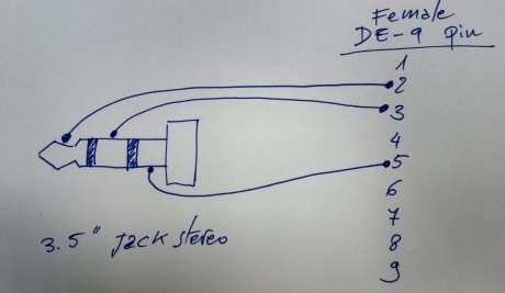
Schema (drawn by myself ):

serial Galileo

The cable will be connected to the Galileo using a devoted female jack 3.5” connector (right, you can’t use it to plug in your earphones! ^__^) and to the host pc via a native RS-232 male connector or (more probably) using a ten-euros Usb-to-Serial converter.

At this point you will connect to the Galileo using a shell program (in Linux and Mac I use Minicom, on Windows I use PuTTY) with the following (I know, you know… they are always the same) parameters:

  • Serial Port: the identifier of the connected port on the host pc (i.e. COMxx, /dev/ttyUsbx etc. depending on your operating system)
  • Speed: 115200 bps
  • Flow Control: None
  • Parity: None
  • Stop bits: 1
  • Data bits: 8

If you prefere a more “network oriented” solutyion, you can use a telnet shell.

In order to do this, you must download a particular sketch via Arduino IDE for Intel Galileo. This sketch will call some Linux system shell commands (yes, you can launch Linux shell scripts using the Arduino skecth programming…it’s very interesting and it is one of the more celebrated features of Intel Galileo!!!).

You can connect the host pc and the Galileo board via cross-patch network cable or using a Fast Ethernet switch between the host pc and the board.

This is the sketch I used . You can copy/paste it on the Arduino IDE then you will download it on Galileo after his boot, lastly open the IDE serial terminal to see the output of linux commands.

//Sketch to connect a PC host to Linux Galileo via telnet 
// Written by M. Lastri fo garretlabs.wordpress.com
//The sketch will:
//1. set the Galileo IP to 169.254.1.1 
//2. start telnet server
//------>>>>>After this the user can:
//3. From the pc host (i.e. with IP =169.254.1.2) send ping 169.254.1.1 and verify the answer
//4. From the host send the famous command "telnet 169.254.1.1"...and the Linux Galileo shell should appear (user: root, no password)!
//5. Enjoy!
void setup() 
{
  system("ifconfig > /dev/ttyGS0");
  system("ifconfig eth0 169.254.1.1 netmask 255.255.0.0 up");
  system("ifconfig > /dev/ttyGS0");
  system("telnetd -l /bin/sh");
}
void loop() 
{
  //nothing here 
}

Important note: someone on internet verified that if Galileo starts without the ethernet cable connected, the telnet server will not start properly, so, ensure that you will power on the Galileo board with the ethernet link connected (directy to the host pc or to the switch).

Another important thing: if using for Galileo and for host pc the well known LAN addresses 192.168.1.x with mask 255.255.255.0, the connection between pc and Galileo doesn’t seem to work in my setup. It is a very strange behavior in my opinion…so we should investigate on it! 😉

In the next post dedicated to Galileo I will start to play with porting sketches (and their problems) from Arduino UNO/Mega ADK  to the Intel platform. Well’ verify that it’s no so simple… or, better,as we say in Italy, “It isn’t all gold which is brilliant” ! 🙂

…Bye (male & female) geeks!

Unpacking (and playing with) the Intel Galileo board: first impressions

Good morning to all you embedded freaks!

Let’s talk a little about Intel Galileo today. Just a “first impression post”… a very light chunk in order to smoothly introduce the argument.

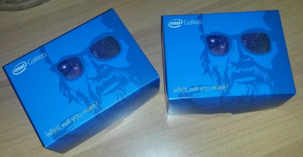
I opened the box some day ago. In the box there is the board and a power cord with ALL possible plugs (so you can use the Galileo everywhere, but ALWAYS with a power socket on the wall! 🙂 ).

galileos

Is it an Arduino Uno or a Linux based embedded board? Mhhh…someone told me it’s a hybrid one between the two things.

But after some very basic experience on this board, I am at the moment very doubtful about the right answer.

In order to do the first (baby) steps with the Galileo board you must use the Quick Start Guide from Intel (you can download it from the official website). It’s a good starting point (since it it the -near- only one!).

After this…it’s up to you guys! 😉

Well, anyway, you must always remember three very important things (the first one is the most important, trust me: it’s veryveryvery important):

  1. You must connect the Galileo power plug BEFORE to connect his USB to the host PC (so, you must disconnect the USB from the host PC BEFORE to disconnect the Galileo power plug). It seems that a incorrect connection/disconnection order could break (…burn?) the Galileo hardware. Arghhhh…too dangerous! 🙂
  2. If you don’t boot the board from a Linux image installed on the microSD, any Arduino sketch downloaded using the IDE on the Galileo board, will be lost at the power off. In order to have a “persistent” sketch (wich it will start his execution after the Galileo boot, exactly as on the Arduino UNO) you must boot the Galileo board starting from the microSD, with the devoted Linux distribution installed on (because in this case the downloaded sketch will be saved in a filesystem folder called /sketches).
  3. All advanced functions, the network drivers and protocols (networl support, telnet and ssh in primis) will work only if booting the Galileo board from the microSD.

I think that these three aspects (especially the first one) will be corrected by Intel in the next release (if there will be…).

The last thing I’ve noticed after two hours of play is very interesting: the Intel Galileo doesn’t have a video output (differently from other embedded Linux solutions such as Raspberry PI). My colleague and friend Paolo noticed it after 5 minutes on the web…but it is more skilled than me on embedded hardware! 😀

Ok, I think it isn’t so necessary but it could be funny. One solution (pay attention: now I’m talking with no idea if it is really possibile/feasible, and how great would be the effort to up’n’run this solution!) to have a video output with a graphic environment could be the use of a X remote screen connecting Galileo to a Linux desktop machine…. it could be one really good idea for a case study (I think I will try in the future)!

Another thing. An annoying thing for me, especially to execute portings from Arduino UNO to Intel Galileo. The hard reality of facts is that … String class doens’t work correctly in the modified Arduino IDE from Intel.

Ok, if no one yet revealed to you this secret (I know it’s a “Pulcinella’s secret” -a very well known secret-, as we say in Italy)… I’m proud to do it. 🙂

The use of String class of Arduino IDE is strongly deprecated (by me, but also by some other desperate people -like me- on internet…) because the String operations such as “+” (concatenation) don’t work. So… if you want to print on the serial output of Arduino side some slightly complicated string….I think you should use only combinations of Serial.print and Serial.println functions. Or, you can try to use the old “C” functions dedicated to string manipulation: strcpy, strcmp, sprintf and so on (as usual defined in the file stdio.h). I’ve done a little tour with these functions and they seem to work (also if I think they are really terrible to be used in 2014…) so, good luck guys!

Well, in the next post we’ll go more into concrete spaces (with some code, I know you love it!). So, have no fear (possibly, have a beer)! 😉

Galileo, Galileo… and me.

…Gooooood morning people!!!

My name is Marco Lastri (ML), I am an italian pro system-software engineer and also a pro-am musician.

I work as software engineering manager in scientific areas tied to artificial satellites. I have approx. 25 years of experience in computer science, algorithms, architectures and programming (I started to program my first computer at 12)…and I play any kind of software and hardware synthesizer. And also a little of drums! 🙂

I am interested in the music-electronics-software interaction (because I am not a good piano player! 🙂 ), so I tried to study Arduino (Intel Galileo), Raspberry PI platform and some other ARM based boards in order to create projects often tied to wearable musical instruments (yes, I love all old-style “keytars” such as Moog Liberation!!! 🙂 ).

2014-02-24 07.45.14

So I decided to try this experience: a personal blog dedicated to my projects and to my ideas, based on open source hardware and software solutions.

…You will find here also tips’n’tricks found during my studies on these “black boxes” (damn’ lack of documentation!) called “embedded boards” !

This blog has been created in collaboration with the SirsLab of Università di Siena and with SirsLab official blog (many thanks to professors Domenico Prattichizzo and Monica Malvezzi), in order to share with the SirsLab people experiences on the wearable controller devices.

Firstly… why Arduino? Because it’s an italian product, an italian (good) idea. Because Italia is not only “spaghetti, pizza, mandolinoand corruption. 😉

…Why open source? Because I think it is the only way to create low price new ideas, also created by unexperienced people (but with great mental strenght!).

…Why an english blog? Beacuse, also if my english is poor, I think it’s a simpler way to share with the internet my ideas and my experience.

…Finally, why this blog is called “ML Garret Labs“? Because at the moment my lab is  in my garret…. 🙂

Bye bye tech-geeks…and stay tuned!

PS: in the photo with Galileo, Galileo and me…  there was also Figaro Magnifico (cit. Queen), but it was too on the right 🙂